Solar-Powered IoT Device with ESP32-CAM, SIM900A GSM, and TOF Sensor Integration
Circuit Documentation
Summary
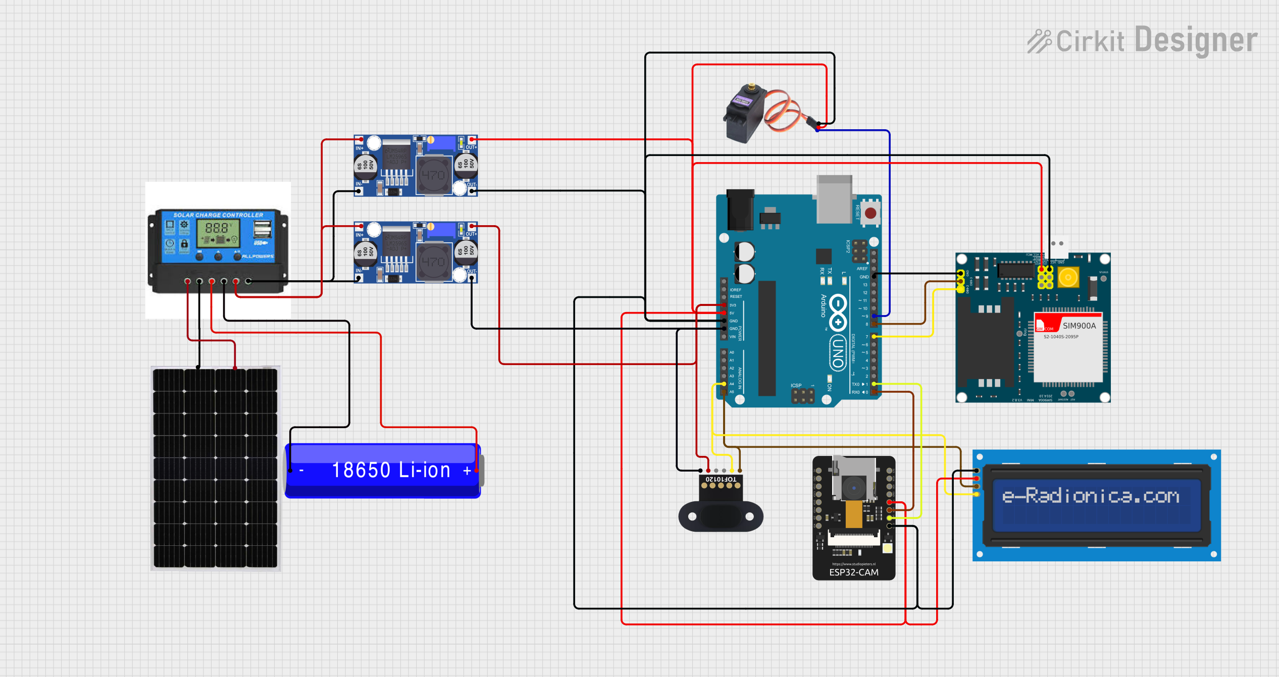
This circuit is designed to integrate various components including a charge controller, solar panel, TOF10120 sensor, SIM900A GSM module, MG996R servo motor, ESP32-CAM module, two buck converters, an 18650 Li-ion battery, an Arduino UNO, and an LCD screen with I2C interface. The circuit is likely intended for a solar-powered system with communication capabilities, distance measurement, image capture, and display functionalities. The Arduino UNO serves as the central microcontroller, interfacing with the sensors, GSM module, camera, and display, while also controlling the servo motor.
Component List
- Charge Controller: Manages the charging of the battery from the solar panel and provides load regulation.
- Solar Panel: Converts sunlight into electrical energy to charge the battery through the charge controller.
- TOF10120: A time-of-flight distance sensor that communicates via I2C and provides distance measurements.
- SIM900A: A GSM module for cellular communication, capable of sending/receiving messages and data.
- MG996R: A high-torque servo motor controlled by a PWM signal.
- ESP32-CAM: A camera module with Wi-Fi capabilities, used for capturing images and possibly video streaming.
- Buck Converter: Two voltage regulators that step down the voltage to a lower level for various components.
- 18650 Li-ion Battery: Provides power storage and supply for the circuit.
- Arduino UNO: The main microcontroller that orchestrates the operation of the entire circuit.
- LCD screen 16x2 I2C: A display module for showing information, interfaced via I2C.
Wiring Details
Charge Controller
- Solar Positive: Connected to Solar Panel positive terminal.
- Solar Negative: Connected to Solar Panel negative terminal.
- Battery Positive: Connected to 18650 Li-ion Battery positive terminal.
- Battery Negative: Connected to 18650 Li-ion Battery negative terminal.
- Load Positive: Connected to the positive input of both Buck Converters.
- Load Negative: Connected to the negative input of both Buck Converters.
Solar Panel
- +: Connected to Charge Controller Solar Positive.
- -: Connected to Charge Controller Solar Negative.
TOF10120
- RXD: (Not specified in net list)
- TXD: (Not specified in net list)
- SDL: Connected to Arduino UNO A4 (SCL).
- VCC: Connected to 3.3V from Arduino UNO via Buck Converter.
- SCL: Connected to Arduino UNO A5 (SDA).
- GND: Connected to common ground.
SIM900A
- GND: Connected to common ground.
- DB9-3 (RXD): Connected to Arduino UNO D8.
- DB9-2 (TXD): Connected to Arduino UNO D7.
- 5V: (Not specified in net list)
- 3VR: (Not specified in net list)
- 5VR: (Not specified in net list)
- 3VT: (Not specified in net list)
- 5VT: (Not specified in net list)
- VCC: Connected to 5V from Arduino UNO via Buck Converter.
- Ring: (Not specified in net list)
- RESTART: (Not specified in net list)
- RESET: (Not specified in net list)
- STATUS: (Not specified in net list)
MG996R
- GND: Connected to common ground.
- VCC: Connected to 5V from Arduino UNO via Buck Converter.
- SIG: Connected to Arduino UNO D9.
ESP32 - CAM
- 5V: (Not specified in net list)
- GND: Connected to common ground.
- IO12: (Not specified in net list)
- IO13: (Not specified in net list)
- IO15: (Not specified in net list)
- IO14: (Not specified in net list)
- IO2: (Not specified in net list)
- IO4: (Not specified in net list)
- VOT: Connected to Arduino UNO D1.
- VOR: Connected to Arduino UNO D0.
- VCC: Connected to 5V from Arduino UNO.
- IO0: (Not specified in net list)
- IO16: (Not specified in net list)
- 3V3: (Not specified in net list)
Buck Converter (Instance 1)
- IN+: Connected to Charge Controller Load Positive.
- IN-: Connected to Charge Controller Load Negative.
- OUT+: Connected to TOF10120 VCC.
- OUT-: Connected to common ground.
Buck Converter (Instance 2)
- IN+: Connected to Charge Controller Load Positive.
- IN-: Connected to Charge Controller Load Negative.
- OUT+: Connected to ESP32-CAM VCC, SIM900A VCC, MG996R VCC, and LCD screen VCC.
- OUT-: Connected to common ground.
18650 Li-ion Battery
- +: Connected to Charge Controller Battery Positive.
- -: Connected to Charge Controller Battery Negative.
Arduino UNO
- 3.3V: Connected to TOF10120 VCC via Buck Converter.
- 5V: Connected to ESP32-CAM VCC, SIM900A VCC, MG996R VCC, and LCD screen VCC via Buck Converter.
- GND: Common ground connection.
- Vin: (Not specified in net list)
- A0-A5: A4 connected to TOF10120 SDL and LCD screen SCL; A5 connected to TOF10120 SCL and LCD screen SDA.
- SCL: (Not specified in net list)
- SDA: (Not specified in net list)
- AREF: (Not specified in net list)
- D0-D13: D9 connected to MG996R SIG; D8 connected to SIM900A RXD; D7 connected to SIM900A TXD; D1 connected to ESP32-CAM VOT; D0 connected to ESP32-CAM VOR.
LCD screen 16x2 I2C
- SCL: Connected to Arduino UNO A4.
- SDA: Connected to Arduino UNO A5.
- VCC: Connected to 5V from Arduino UNO via Buck Converter.
- GND: Connected to common ground.
Documented Code
Arduino UNO Code (sketch.ino)
void setup() {
  // put your setup code here, to run once:

}

void loop() {
  // put your main code here, to run repeatedly:

}
Note: The provided code is a template and does not include specific functionality. It needs to be populated with the setup and loop code to control and interact with the connected components.