
Arduino Uno R3 and DFPlayer Mini-Based Interactive Color Sensor with Audio Feedback
View and Edit Project In Cirkit Designer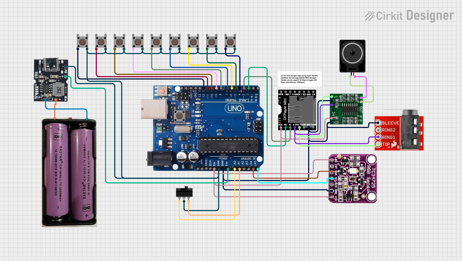
Circuit Documentation
Summary
This circuit is designed to interface an Arduino Uno R3 with various components including a DFPlayer Mini, a PAM8403 amplifier, a TCS3472 color sensor, multiple pushbuttons, a toggle switch, a TRRS 3.5mm jack breakout, a loudspeaker, and a Type-C power bank module. The Arduino Uno R3 serves as the central microcontroller, controlling the DFPlayer Mini for audio playback, reading inputs from pushbuttons and a toggle switch, and interfacing with the TCS3472 color sensor for color detection.
Component List
Arduino Uno R3
- Description: Microcontroller board based on the ATmega328P.
- Pins: USB Port, Power Jack, Not Connected, IOREF, RESET, 3.3V, 5V, GND, VIN, A0, A1, A2, A3, A4/SDA, A5/SCL, SCL, SDA, AREF, 13, 12, 11, 10, 9, 8, 7, 6, 5, 4, 3, 2, 1, 0
DFPlayer Mini
- Description: A small MP3 player module that can be controlled via serial communication.
- Pins: VCC, BUSY, RX, USB -, TX, USB +, DAC_R, K2/ADC_KEY, DAC_L, K1/ADC_KEY, SPK1, IO 2, GND, SPK2, IO 1
Toggle Switch
- Description: A switch that can toggle between two states.
- Pins: L1, COM, L2
TCS3472 Color Light-to-Digital Converter with IR Filter
- Description: A color sensor that converts light to digital values.
- Pins: LED, INT, SDA, SCL, 3V3, GND, VIN
Pushbutton
- Description: A simple pushbutton switch.
- Pins: Pin 3 (out), Pin 4 (out), Pin 1 (in), Pin 2 (in)
PAM8403
- Description: A small digital amplifier module.
- Pins: 5vIN+, GND/IN-, R-INPUT, GND, L-INPUT, L-, L+, R+, R-
TRRS 3.5mm Jack Breakout
- Description: A breakout board for a 3.5mm TRRS jack.
- Pins: Sleeve, Ring2, Ring1, Tip
Loudspeaker
- Description: A speaker for audio output.
- Pins: pin1, pin2
7.4v Battery
- Description: A 7.4V battery for power supply.
- Pins: +, -
Type-C Power Bank Module
- Description: A power bank module with Type-C interface.
- Pins: Gnd, +Ve (Bat), +5v
Wiring Details
Arduino Uno R3
- 5V: Connected to VCC of DFPlayer Mini, 5vIN+ of PAM8403, LED and VIN of TCS3472 Color Sensor.
- GND: Connected to GND of DFPlayer Mini, GND/IN- and GND of PAM8403, GND of TCS3472 Color Sensor, and Sleeve of TRRS 3.5mm Jack Breakout.
- VIN: Connected to +5v of Type-C Power Bank Module.
- A0: Connected to L1 of Toggle Switch.
- A1: Connected to L2 of Toggle Switch.
- A4/SDA: Connected to SDA of TCS3472 Color Sensor.
- A5/SCL: Connected to SCL of TCS3472 Color Sensor.
- Digital Pin 2: Connected to RX of DFPlayer Mini.
- Digital Pin 3: Connected to TX of DFPlayer Mini.
- Digital Pin 4: Connected to Pin 2 (in) of Pushbutton.
- Digital Pin 5: Connected to Pin 2 (in) of Pushbutton.
- Digital Pin 6: Connected to Pin 2 (in) of Pushbutton.
- Digital Pin 7: Connected to Pin 2 (in) of Pushbutton.
- Digital Pin 8: Connected to Pin 2 (in) of Pushbutton.
- Digital Pin 9: Connected to Pin 2 (in) of Pushbutton.
- Digital Pin 10: Connected to Pin 2 (in) of Pushbutton.
- Digital Pin 11: Connected to Pin 2 (in) of Pushbutton.
- Digital Pin 12: Connected to Pin 2 (in) of Pushbutton.
DFPlayer Mini
- VCC: Connected to 5V of Arduino Uno R3.
- GND: Connected to GND of Arduino Uno R3.
- RX: Connected to Digital Pin 2 of Arduino Uno R3.
- TX: Connected to Digital Pin 3 of Arduino Uno R3.
- DAC_R: Connected to R-INPUT of PAM8403 and Ring1 of TRRS 3.5mm Jack Breakout.
- DAC_L: Connected to L-INPUT of PAM8403 and Tip of TRRS 3.5mm Jack Breakout.
Toggle Switch
- L1: Connected to A0 of Arduino Uno R3.
- COM: Connected to GND of Arduino Uno R3.
- L2: Connected to A1 of Arduino Uno R3.
TCS3472 Color Light-to-Digital Converter with IR Filter
- LED: Connected to 5V of Arduino Uno R3.
- GND: Connected to GND of Arduino Uno R3.
- VIN: Connected to 5V of Arduino Uno R3.
- SDA: Connected to A4/SDA of Arduino Uno R3.
- SCL: Connected to A5/SCL of Arduino Uno R3.
Pushbutton
- Pin 2 (in): Connected to Digital Pins 4, 5, 6, 7, 8, 9, 10, 11, 12 of Arduino Uno R3.
- Pin 4 (out): Connected to GND of Arduino Uno R3.
PAM8403
- 5vIN+: Connected to 5V of Arduino Uno R3.
- GND/IN-: Connected to GND of Arduino Uno R3.
- R-INPUT: Connected to DAC_R of DFPlayer Mini.
- L-INPUT: Connected to DAC_L of DFPlayer Mini.
- L-: Connected to pin2 of Loudspeaker.
- L+: Connected to pin1 of Loudspeaker.
TRRS 3.5mm Jack Breakout
- Sleeve: Connected to GND of Arduino Uno R3.
- Ring1: Connected to DAC_R of DFPlayer Mini.
- Tip: Connected to DAC_L of DFPlayer Mini.
Loudspeaker
- pin1: Connected to L+ of PAM8403.
- pin2: Connected to L- of PAM8403.
7.4v Battery
- +: Connected to +Ve (Bat) of Type-C Power Bank Module.
- -: Connected to Gnd of Type-C Power Bank Module.
Type-C Power Bank Module
- Gnd: Connected to GND of Arduino Uno R3.
- +5v: Connected to VIN of Arduino Uno R3.
- +Ve (Bat): Connected to + of 7.4v Battery.
Documented Code
#include <EEPROM.h>
#include <Adafruit_TCS34725.h>
#include <Wire.h>
#include <DFPlayer_Mini_Mp3.h>
#include "SoftwareSerial.h"
//#include "DFRobotDFPlayerMini.h"
static const uint8_t PIN_MP3_TX = 3; // Connects to module's RX
static const uint8_t PIN_MP3_RX = 2; // Connects to module's TX
SoftwareSerial softwareSerial(PIN_MP3_RX, PIN_MP3_TX);
// Create the Player object
//DFRobotDFPlayerMini player;

int tb1=4;
int tb2=5;
int tb3=6;
int tb4=9;
int tb5=8;
int tb6=7;
int tb7=10;
int tb8=11;
int tb9=12;

int bc1;
int bc2;
int bc3;
int bc4;
int bc5;
int bc6;
int bc7;
int bc8;
int bc9;

Adafruit_TCS34725 tcs = Adafruit_TCS34725(TCS34725_INTEGRATIONTIME_50MS, TCS34725_GAIN_4X);

byte R=0;
byte G=0;
byte B=0;
byte Ra;
byte Rb;
byte Ga;
byte Gb;
byte Ba;
byte Bb;

int nilai;
char kal;

void setup() {
  pinMode(tb1,INPUT_PULLUP);
  pinMode(tb2,INPUT_PULLUP);
  pinMode(tb3,INPUT_PULLUP);
  pinMode(tb4,INPUT_PULLUP);
  pinMode(tb5,INPUT_PULLUP);
  pinMode(tb6,INPUT_PULLUP);
  pinMode(tb7,INPUT_PULLUP);
  pinMode(tb8,INPUT_PULLUP);
  pin