
ESP32 and ESP32-CAM Based Wireless Temperature Monitoring System
View and Edit Project In Cirkit Designer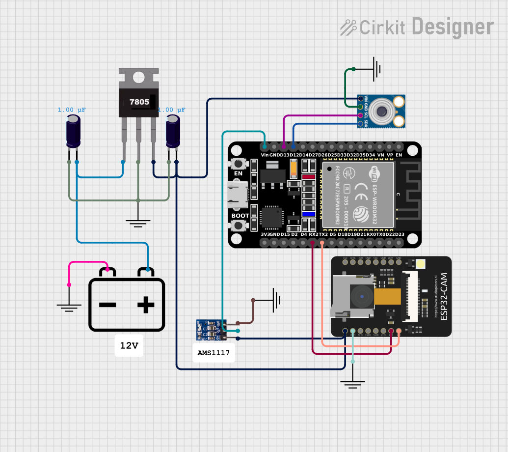
Circuit Documentation
Summary
This circuit involves an ESP32 microcontroller, an ESP32-CAM module, a 7805 voltage regulator, an AMS1117 3.3V voltage regulator, an MLX90614 infrared temperature sensor, and a 12V battery. The circuit is designed to power the ESP32 and ESP32-CAM modules, and interface the ESP32 with the MLX90614 sensor for temperature measurements.
Component List
ESP32 (30 pin)
- Description: A powerful microcontroller with Wi-Fi and Bluetooth capabilities.
- Pins: EN, VP, VN, D34, D35, D32, D33, D25, D26, D27, D14, D12, D13, GND, Vin, D23, D22, TX0, RX0, D21, D19, D18, D5, TX2, RX2, D4, D2, D15, 3V3
7805
- Description: A voltage regulator that outputs 5V.
- Pins: Vin, Gnd, Vout
MLX90614
- Description: An infrared temperature sensor.
- Pins: SDA, SCL, GND, VIN
GND
- Description: Ground connection.
- Pins: GND
Electrolytic Capacitor
- Description: A capacitor with a capacitance of 1µF.
- Pins: -, +
ESP32-CAM
- Description: A camera module with an ESP32 microcontroller.
- Pins: 5V, GND, IO12, IO13, IO15, IO14, IO2, IO4, VOT, VOR, VCC, IO0, IO16, 3V3
12V Battery
- Description: A 12V power source.
- Pins: -, +
AMS1117 3.3
- Description: A voltage regulator that outputs 3.3V.
- Pins: VIN, OUT, GND
Wiring Details
ESP32 (30 pin)
- D12 is connected to SDA of the MLX90614.
- D13 is connected to SCL of the MLX90614.
- Vin is connected to OUT of the AMS1117 3.3.
- TX2 is connected to IO4 of the ESP32-CAM.
- RX2 is connected to IO2 of the ESP32-CAM.
7805
- Vin is connected to + of the Electrolytic Capacitor and + of the 12V Battery.
- Gnd is connected to - of the Electrolytic Capacitor and GND.
- Vout is connected to VIN of the MLX90614, 5V of the ESP32-CAM, and VIN of the AMS1117 3.3.
MLX90614
- SDA is connected to D12 of the ESP32.
- SCL is connected to D13 of the ESP32.
- GND is connected to GND.
- VIN is connected to Vout of the 7805.
ESP32-CAM
- 5V is connected to Vout of the 7805.
- GND is connected to GND.
- IO4 is connected to TX2 of the ESP32.
- IO2 is connected to RX2 of the ESP32.
Electrolytic Capacitor
- + is connected to Vin of the 7805 and + of the 12V Battery.
- - is connected to GND.
12V Battery
- + is connected to + of the Electrolytic Capacitor and Vin of the 7805.
- - is connected to GND.
AMS1117 3.3
- VIN is connected to Vout of the 7805.
- OUT is connected to Vin of the ESP32.
- GND is connected to GND.
Documented Code
There is no code provided for this circuit.