
Circuit Documentation
Summary
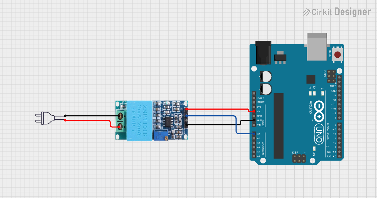
This circuit involves an Arduino UNO microcontroller interfaced with a ZMPT101B voltage sensor module. The ZMPT101B is connected to a 220V power source to measure the voltage. The Arduino UNO reads the voltage data from the ZMPT101B and can be programmed to process or display this data.
Component List
Arduino UNO
- Description: A microcontroller board based on the ATmega328P.
- Pins: UNUSED, IOREF, Reset, 3.3V, 5V, GND, Vin, A0, A1, A2, A3, A4, A5, SCL, SDA, AREF, D13, D12, D11, D10, D9, D8, D7, D6, D5, D4, D3, D2, D1, D0
ZMPT101B
- Description: A voltage sensor module used for measuring AC voltage.
- Pins: OUT, GND, VCC, NEUTRO, FASE
Power 220V
- Description: A 220V AC power source.
- Pins: hot wire, neutral wire
Wiring Details
Arduino UNO
- 5V: Connected to VCC of ZMPT101B
- GND: Connected to GND of ZMPT101B
- A0: Connected to OUT of ZMPT101B
ZMPT101B
- VCC: Connected to 5V of Arduino UNO
- GND: Connected to GND of Arduino UNO
- OUT: Connected to A0 of Arduino UNO
- NEUTRO: Connected to neutral wire of power 220V
- FASE: Connected to hot wire of power 220V
Power 220V
- neutral wire: Connected to NEUTRO of ZMPT101B
- hot wire: Connected to FASE of ZMPT101B
Code Documentation
Arduino UNO Code
sketch.ino
void setup() {
  // put your setup code here, to run once:

}

void loop() {
  // put your main code here, to run repeatedly:

}
documentation.txt