Cirkit Designer
Your all-in-one circuit design IDE
Home /
Project Documentation
Arduino-Controlled Environmental Response Robot with Air Quality Monitoring
Circuit Documentation
Summary
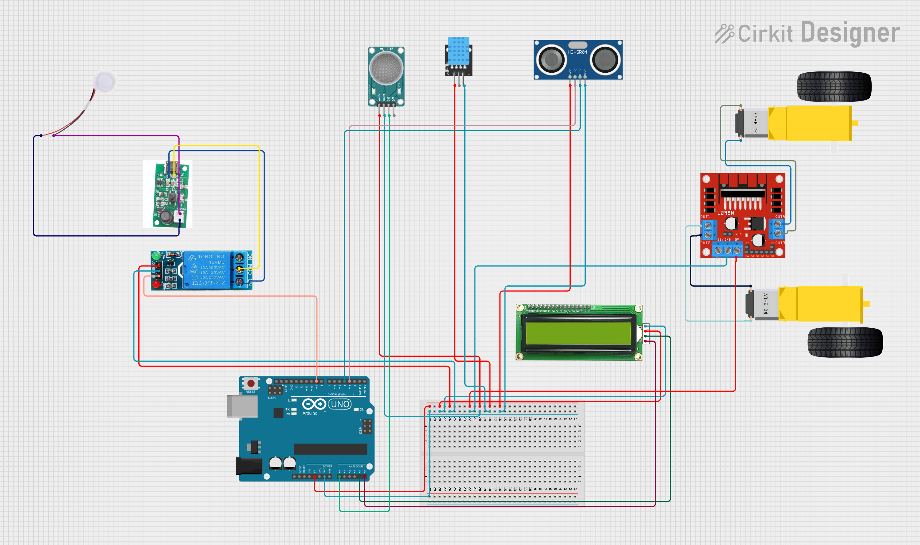
This document provides a detailed overview of a circuit designed to interface various sensors and actuators with an Arduino UNO microcontroller. The circuit includes a USB driver circuit for a fogger atomizer, a 12V single-channel relay, a humidifier, an MQ-135 air quality sensor, a KY-015 DHT11 temperature and humidity sensor, an HC-SR04 ultrasonic sensor, two gearmotors with a corresponding L298N DC motor driver, and an MKE-M07 LCD1602 I2C display module.
Component List
USB Driver Circuit Fogger Atomizer
- Pins:
+,- - Description: Drives the fogger atomizer.
12V Single Channel Relay
- Pins:
NC,COM,NO,IN,GND,VCC - Description: Controls high power devices with Arduino's low power signals.
Humidifier
- Pins:
GND,5V - Description: Adds moisture to the air.
MQ-135 Sensor Air Quality
- Pins:
VCC,GND,A0,D0 - Description: Measures air quality.
KY-015 DHT11
- Pins:
5V,S,GND - Description: Measures temperature and humidity.
HC-SR04 Ultrasonic Sensor
- Pins:
VCC,TRIG,ECHO,GND - Description: Measures distance using ultrasonic waves.
Gearmotor DC Wheels Right
- Pins:
PIN1,PIN2 - Description: Provides motion to the right wheel.
Gearmotor DC Wheels Left
- Pins:
PIN1,PIN2 - Description: Provides motion to the left wheel.
L298N DC Motor Driver
- Pins:
OUT1,OUT2,12V,GND,5V,OUT3,OUT4,5V-ENA-JMP-I,5V-ENA-JMP-O,+5V-J1,+5V-J2,ENA,IN1,IN2,IN3,IN4,ENB - Description: Drives DC motors with direction and speed control.
Arduino UNO
- Pins:
UNUSED,IOREF,Reset,3.3V,5V,GND,Vin,A0,A1,A2,A3,A4,A5,SCL,SDA,AREF,D13,D12,D11,D10,D9,D8,D7,D6,D5,D4,D3,D2,D1,D0 - Description: Microcontroller board based on the ATmega328P.
MKE-M07 LCD1602 I2C
- Pins:
GND,5V,SDA,SCL - Description: Displays information to the user.
Wiring Details
USB Driver Circuit Fogger Atomizer
+connected to 12V Single Channel RelayCOM-connected to 12V Single Channel RelayNOand HumidifierGND
12V Single Channel Relay
NCnot connectedCOMconnected to USB Driver Circuit Fogger Atomizer+NOconnected to USB Driver Circuit Fogger Atomizer-INconnected to Arduino UNOD9GNDconnected to common groundVCCconnected to common 5V
Humidifier
5Vconnected to USB Driver Circuit Fogger Atomizer+GNDconnected to USB Driver Circuit Fogger Atomizer-
MQ-135 Sensor Air Quality
VCCconnected to common 5VGNDconnected to common groundA0connected to Arduino UNOA0D0not connected
KY-015 DHT11
5Vconnected to common 5VSnot connectedGNDconnected to common ground
HC-SR04 Ultrasonic Sensor
VCCconnected to common 5VTRIGconnected to Arduino UNOD3ECHOconnected to Arduino UNOD4GNDconnected to common ground
Gearmotor DC Wheels Right
PIN1connected to L298N DC Motor DriverOUT3PIN2connected to L298N DC Motor DriverOUT4
Gearmotor DC Wheels Left
PIN1connected to L298N DC Motor DriverOUT2PIN2connected to L298N DC Motor DriverOUT1
L298N DC Motor Driver
OUT1connected to Gearmotor DC Wheels LeftPIN2OUT2connected to Gearmotor DC Wheels LeftPIN112Vnot connectedGNDconnected to common ground5Vconnected to common 5VOUT3connected to Gearmotor DC Wheels RightPIN1OUT4connected to Gearmotor DC Wheels RightPIN2- Remaining pins not connected or used for internal jumper settings
Arduino UNO
5Vconnected to common 5VGNDconnected to common groundA0connected to MQ-135 Sensor Air QualityA0A4connected to MKE-M07 LCD1602 I2CSDAA5connected to MKE-M07 LCD1602 I2CSCLD3connected to HC-SR04 Ultrasonic SensorTRIGD4connected to HC-SR04 Ultrasonic SensorECHOD9connected to 12V Single Channel RelayIN- Remaining pins not connected
MKE-M07 LCD1602 I2C
GNDconnected to common ground5Vconnected to common 5VSDAconnected to Arduino UNOA4SCLconnected to Arduino UNOA5
Documented Code
Arduino UNO Code (sketch.ino)
void setup() {
  // put your setup code here, to run once:

}

void loop() {
  // put your main code here, to run repeatedly:

}
Additional Notes
- The code provided for the Arduino UNO is a template with empty
setup()andloop()functions. Actual implementation details need to be filled in based on the specific requirements of the circuit's operation. - The
documentation.txtfile is empty and does not contain any additional information.