Cirkit Designer
Your all-in-one circuit design IDE
Home /
Project Documentation
Arduino UNO Based Smoke Detection System with Audible Alert
Circuit Documentation
Summary of the Circuit
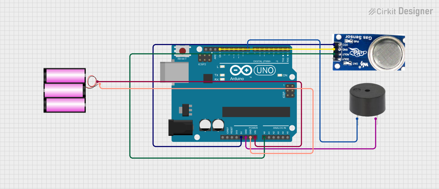
This circuit is designed to interface an Arduino UNO with a smoke sensor and a buzzer. The Arduino UNO acts as the central processing unit, reading the analog output from the smoke sensor and controlling the buzzer based on the sensor's readings. The circuit is powered by a 12V battery, which is stepped down to 5V by the Arduino's onboard voltage regulator to power the smoke sensor. The buzzer is directly driven by one of the Arduino's digital I/O pins.
Component List
Arduino UNO
- Description: A microcontroller board based on the ATmega328P.
- Pins: UNUSED, IOREF, Reset, 3.3V, 5V, GND, Vin, A0-A5, SCL, SDA, AREF, D0-D13.
Smoke Sensor
- Description: A sensor capable of detecting smoke particles in the air.
- Pins: DO (Digital Output), AO (Analog Output), GND (Ground), VCC (Power Supply).
Buzzer
- Description: An electromechanical component that emits sound when powered.
- Pins: PIN (Signal Input), GND (Ground).
Battery 12V
- Description: A power source providing 12 volts.
- Pins: + (Positive), - (Negative).
Wiring Details
Arduino UNO
- 5V connected to Smoke Sensor VCC.
- GND connected to Smoke Sensor GND, Buzzer GND, and Battery 12V -.
- Vin connected to Battery 12V +.
- A0 connected to Smoke Sensor AO.
- D8 connected to Buzzer PIN.
Smoke Sensor
- VCC connected to Arduino UNO 5V.
- GND connected to Arduino UNO GND.
- AO connected to Arduino UNO A0.
Buzzer
- PIN connected to Arduino UNO D8.
- GND connected to Arduino UNO GND.
Battery 12V
- + connected to Arduino UNO Vin.
- - connected to Arduino UNO GND.
Documented Code
Arduino UNO Code (sketch.ino)
void setup() {
  // put your setup code here, to run once:

}

void loop() {
  // put your main code here, to run repeatedly:

}
Note: The provided code is a template and does not include functionality. To complete the circuit's purpose, the code needs to be written to read the analog value from the smoke sensor and activate the buzzer under certain conditions.