
Circuit Documentation
Summary of the Circuit
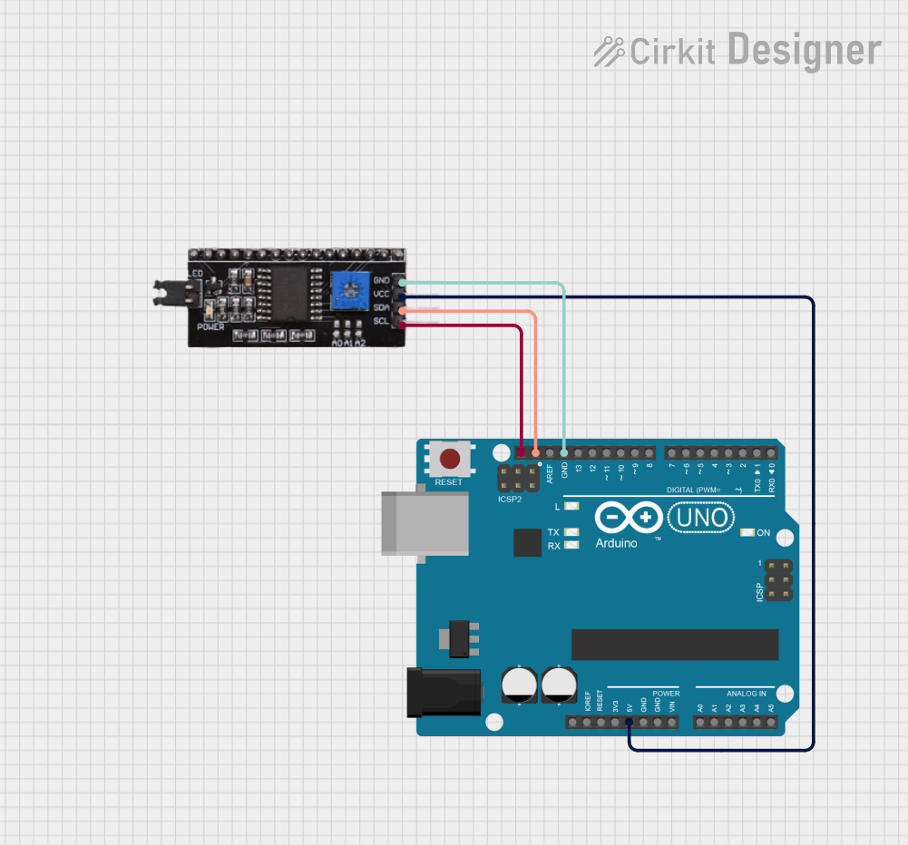
This circuit consists of an Arduino UNO microcontroller board interfaced with an I2C module. The Arduino UNO serves as the central processing unit, controlling the I2C module, which could be a sensor or any device that communicates over the I2C bus. The connections between the Arduino UNO and the I2C module are established through the I2C communication lines (SCL and SDA), as well as power (5V to VCC) and ground connections.
Component List
Arduino UNO
- Description: A microcontroller board based on the ATmega328P.
- Pins Used:
5V: Provides power to the I2C module.GND: Common ground for the circuit.SCL: I2C clock line.SDA: I2C data line.
I2C Module
- Description: A generic I2C communication module.
- Pins Used:
VCC: Receives power from the Arduino UNO.GND: Common ground for the circuit.SCL: I2C clock line connected to Arduino UNO.SDA: I2C data line connected to Arduino UNO.
Wiring Details
Arduino UNO
5Vto I2C moduleVCCGNDto I2C moduleGNDSCLto I2C moduleSCLSDAto I2C moduleSDA
I2C Module
VCCconnected to Arduino UNO5VGNDconnected to Arduino UNOGNDSCLconnected to Arduino UNOSCLSDAconnected to Arduino UNOSDA
Documented Code
Arduino UNO Code (sketch.ino)
void setup() {
  // put your setup code here, to run once:

}

void loop() {
  // put your main code here, to run repeatedly:

}
Additional Notes
- The provided code is a template and does not contain any specific instructions for interacting with the I2C module. The user should add the necessary code to initialize the I2C communication and handle data transfer in the
setup()andloop()functions, respectively. - The
documentation.txtfile is empty and can be used to add additional notes or documentation related to the code or circuit operation.