
Circuit Documentation
Summary
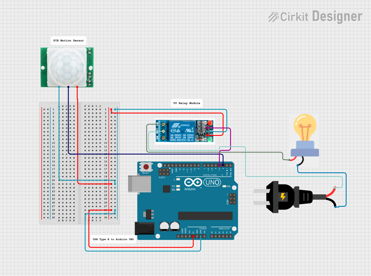
This circuit is designed to control a bulb using a motion sensor and a relay, all managed by an Arduino UNO. When motion is detected by the HC-SR501 motion sensor, the Arduino UNO triggers the 5V relay to turn on the bulb. The circuit is powered by an AC source.
Component List
AC Source
- Description: Provides AC power to the circuit.
- Pins: +, -
5V Relay
- Description: Acts as a switch to control the bulb based on the signal from the Arduino.
- Pins: Normally Open, Common terminal, Normally Closed, In, GND, VCC
HC-SR501 Motion Sensor
- Description: Detects motion and sends a signal to the Arduino.
- Pins: GND, OUT, VCC
Bulb
- Description: The load that is controlled by the relay.
- Pins: GND, power
Arduino UNO
- Description: Microcontroller that processes the signal from the motion sensor and controls the relay.
- Pins: UNUSED, IOREF, Reset, 3.3V, 5V, GND, Vin, A0, A1, A2, A3, A4, A5, SCL, SDA, AREF, D13, D12, D11, D10, D9, D8, D7, D6, D5, D4, D3, D2, D1, D0
Wiring Details
AC Source
- +: Connected to the Common terminal of the 5V relay.
- -: Connected to the GND of the bulb.
5V Relay
- VCC: Connected to the 5V pin of the Arduino UNO and the VCC pin of the HC-SR501 motion sensor.
- GND: Connected to the GND pin of the Arduino UNO and the GND pin of the HC-SR501 motion sensor.
- In: Connected to the D3 pin of the Arduino UNO.
- Normally Open: Connected to the power pin of the bulb.
- Common terminal: Connected to the + pin of the AC source.
HC-SR501 Motion Sensor
- GND: Connected to the GND pin of the Arduino UNO and the GND pin of the 5V relay.
- OUT: Connected to the D2 pin of the Arduino UNO.
- VCC: Connected to the 5V pin of the Arduino UNO and the VCC pin of the 5V relay.
Bulb
- GND: Connected to the - pin of the AC source.
- Power: Connected to the Normally Open pin of the 5V relay.
Arduino UNO
- 5V: Connected to the VCC pin of the 5V relay and the VCC pin of the HC-SR501 motion sensor.
- GND: Connected to the GND pin of the 5V relay and the GND pin of the HC-SR501 motion sensor.
- D3: Connected to the In pin of the 5V relay.
- D2: Connected to the OUT pin of the HC-SR501 motion sensor.
Documented Code
sketch.ino
void setup() {
  // put your setup code here, to run once:

}

void loop() {
  // put your main code here, to run repeatedly:

}
documentation.txt