
Wi-Fi Controlled Multi-Color LED System Using NodeMCU ESP8266
View and Edit Project In Cirkit Designer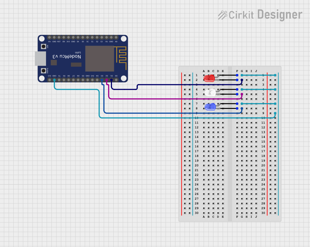
Circuit Documentation
Summary
This circuit involves a NodeMCU V3 ESP8266 microcontroller connected to three LEDs (red, blue, and white). The LEDs are controlled by the NodeMCU through its digital pins, allowing for individual control of each LED.
Component List
NodeMCU V3 ESP8266
- Description: A low-cost Wi-Fi microcontroller with GPIO, PWM, ADC, and more.
- Pins: A0, GND, VU, S3, S2, S1, SC, S0, SK, 3V3, EN, RST, Vin, D0, D1, D2, D3, D4, D5, D6, D7, D8, RX, TX
LED: Two Pin (red)
- Description: A red LED with two pins: cathode and anode.
- Pins: cathode, anode
LED: Two Pin (blue)
- Description: A blue LED with two pins: cathode and anode.
- Pins: cathode, anode
LED: Two Pin (white)
- Description: A white LED with two pins: cathode and anode.
- Pins: cathode, anode
Wiring Details
NodeMCU V3 ESP8266
- D1 is connected to the cathode of the red LED.
- D2 is connected to the cathode of the white LED.
- D3 is connected to the cathode of the blue LED.
- GND is connected to the anode of the red LED, white LED, and blue LED.
LED: Two Pin (red)
- cathode is connected to D1 of the NodeMCU.
- anode is connected to GND of the NodeMCU.
LED: Two Pin (blue)
- cathode is connected to D3 of the NodeMCU.
- anode is connected to GND of the NodeMCU.
LED: Two Pin (white)
- cathode is connected to D2 of the NodeMCU.
- anode is connected to GND of the NodeMCU.
Code
No code is provided for this circuit.