
Autonomous Obstacle-Avoiding Robot with RFID and Bluetooth Control
View and Edit Project In Cirkit Designer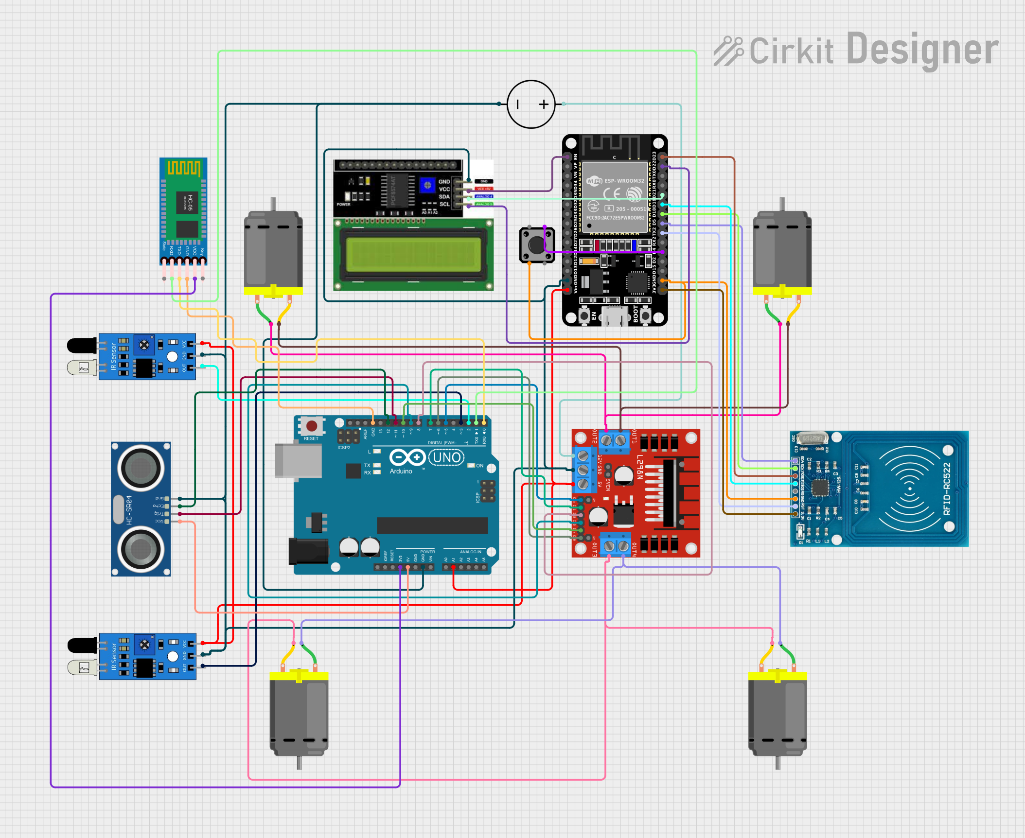
Circuit Documentation
Summary
The circuit in question appears to be a complex system involving sensors, actuators, a microcontroller, and communication modules. The primary controller is an Arduino UNO, which interfaces with IR sensors, an HC-SR04 Ultrasonic Sensor, DC motors through an L298N motor driver, an RFID-RC522 module, an LCD I2C display, an ESP32 module, tactile switches, and an HC-05 Bluetooth module. The circuit is powered by a DC power source. The Arduino UNO is programmed to interact with these components, likely for sensing, actuation, and communication purposes.
Component List
Sensors
- IR Sensors: Used for detecting proximity or presence of objects.
- HC-SR04 Ultrasonic Sensor: Used for measuring distances using ultrasonic waves.
Actuators
- DC Motors: Four motors are present in the circuit for movement or mechanical actuation.
Motor Driver
- L298N DC Motor Driver: Interfaces with the DC motors to control their speed and direction.
Power
- DC Power Source: Supplies power to the circuit.
Controllers
- Arduino UNO: The main microcontroller board for controlling the sensors, actuators, and communication modules.
- ESP32 (30 pin): A powerful microcontroller with Wi-Fi and Bluetooth capabilities.
Communication Modules
- RFID-RC522: An RFID reader for contactless communication.
- HC-05 Bluetooth Module: Enables Bluetooth communication for the circuit.
Display
- LCD I2C Display: An alphanumeric display for showing information.
Input
- Tactile Switch Buttons - 12mm Square: Provides a user interface for input.
Wiring Details
IR Sensors
IR Sensor 1:
outconnected to Arduino UNOD2gndconnected to common groundvccconnected to a voltage source
IR Sensor 2:
outconnected to Arduino UNOD3gndconnected to common groundvccconnected to a voltage source
HC-SR04 Ultrasonic Sensor
VCCconnected to Arduino UNO5VTRIGconnected to Arduino UNOD11ECHOconnected to Arduino UNOD12GNDconnected to common ground
DC Motors
- Motors connected to L298N DC motor driver
OUT1,OUT2,OUT3,OUT4
L298N DC Motor Driver
12Vconnected to DC Power SourcePositiveGNDconnected to common ground5Vconnected to a voltage sourceENA,ENBconnected to Arduino UNOD5,D6IN1,IN2,IN3,IN4connected to Arduino UNOD7,D8,D9,D10
DC Power Source
Groundconnected to common groundPositiveconnected to L298N DC motor driver12V
Arduino UNO
GNDconnected to common ground3.3Vconnected to HC-05 Bluetooth ModuleVCC- Digital and analog pins connected to various components as detailed above
RFID-RC522
VCC (3.3V)connected to ESP323V3RSTconnected to ESP32TX2GNDconnected to common groundMISO,MOSI,SCK,SDAconnected to ESP32D19,D23,D18,D5
LCD I2C Display
VCCconnected to ESP32ENGNDconnected to common groundSDA,SCLconnected to ESP32D21,D22
ESP32 (30 pin)
GNDconnected to common groundVinconnected to a voltage source- Various GPIOs connected to RFID-RC522 and LCD I2C Display
Tactile Switch Buttons - 12mm Square
- One side connected to common ground
- The other side connected to ESP32
D4
HC-05 Bluetooth Module
VCCconnected to Arduino UNO3.3VGNDconnected to common groundTXD,RXDconnected to Arduino UNOD0,D1
Documented Code
Arduino UNO Code (sketch.ino)
void setup() {
  // put your setup code here, to run once:

}

void loop() {
  // put your main code here, to run repeatedly:

}
Note: The code provided for the Arduino UNO is a template and does not contain any functional code. It needs to be populated with the logic to control and interact with the connected components.
ESP32 Code
No code was provided for the ESP32 microcontroller.
Additional Notes
- The documentation file for the Arduino UNO is empty and does not provide any additional information.
- The circuit's functionality and the interaction between components are not detailed in the provided code.