Raspberry Pi 4B-Based Smart Environmental Monitoring and Control System
Circuit Documentation
Summary
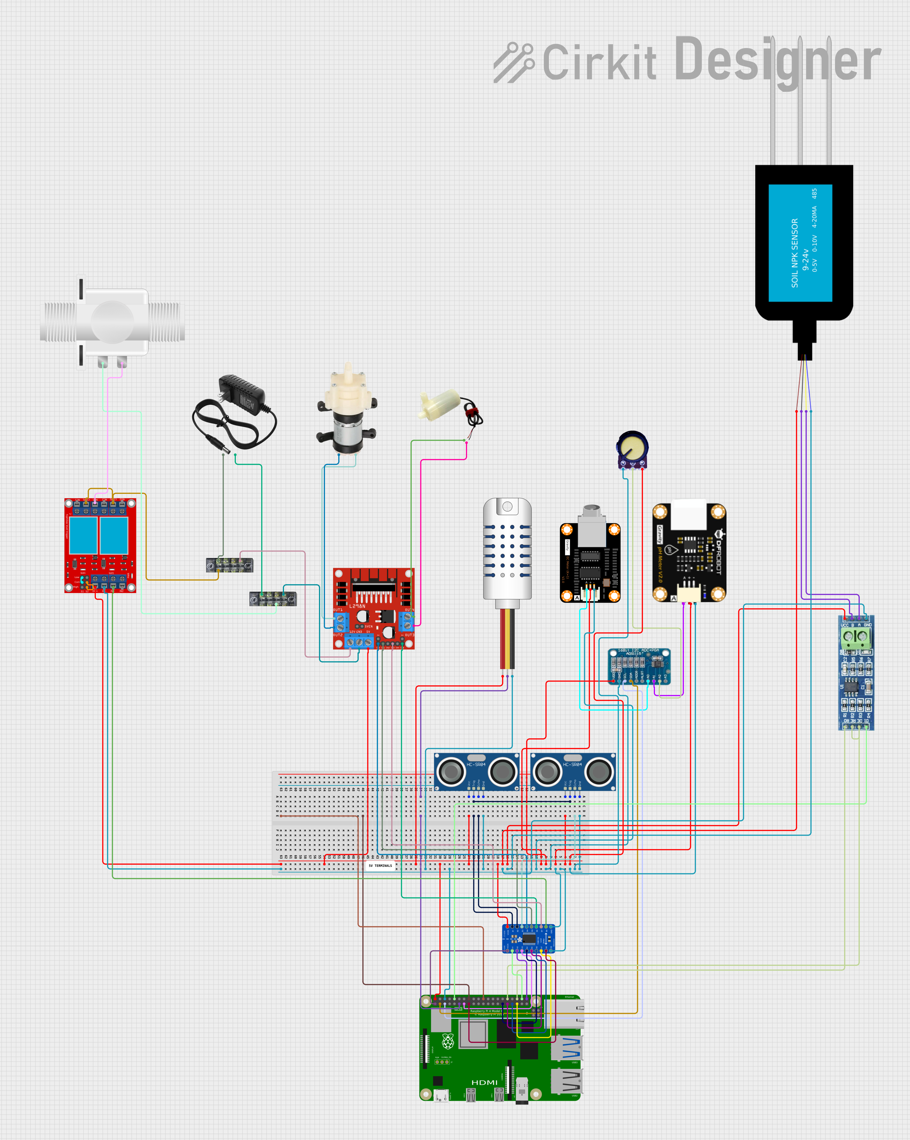
This document provides a detailed overview of a circuit designed to interface various sensors, actuators, and modules with a Raspberry Pi 4B microcontroller. The circuit includes components for sensing temperature, humidity, and distance, as well as controlling water pumps and a solenoid valve. Communication with some sensors is facilitated by an ADS1115 analog-to-digital converter and an RS485 transceiver. A logic level converter is used to interface 3.3V and 5V logic levels, and a motor driver controls the pumps. Power is supplied by a 12V power supply, and a 2-channel relay module is included for switching high-power devices.
Component List
- Raspberry Pi 4B: A microcontroller board with multiple GPIO pins for interfacing with various components.
- Mini Diaphragm Water Pump: A pump for moving water, controlled by the motor driver.
- L298N DC Motor Driver: A module for controlling DC motors, used here to control the water pumps.
- 12V Power Supply: Provides power to the motor driver and the 12V rail of the circuit.
- Terminal Blocks: Used for organizing and connecting wires in the circuit.
- AM2302 Humidity and Temperature Sensor: Measures ambient temperature and humidity.
- 5V Mini Water Pump: Another pump for moving water, also controlled by the motor driver.
- Plastic Solenoid Valve: An electrically-controlled valve for controlling fluid flow.
- HC-SR04 Ultrasonic Sensors: Measure distance by emitting and receiving ultrasonic waves.
- 2-Channel Relay Module: Allows the Raspberry Pi to control high-power devices.
- DFRobot EC Sensor: Measures the electrical conductivity of a solution, indicative of its salt concentration.
- ADS1115: A 16-bit analog-to-digital converter for reading analog sensors.
- Adafruit TXB0108 8-Channel Bi-Directional Logic Level Converter: Converts logic levels between 3.3V and 5V.
- pH Degree Sensor Module: Measures the pH level of a solution.
- NPK Soil Sensor: Measures the nitrogen, phosphorus, and potassium content in soil.
- RS485 Transceiver: Facilitates RS485 communication for long-distance and differential signaling.
- Potentiometer: A variable resistor, typically used for adjusting a parameter or as a sensor input.
Wiring Details
Raspberry Pi 4B
- 3V3: Logic level converter (VCCA)
- 5V: Powers various 5V components and sensors
- GPIO2 (SDA): Connected to ADS1115 (SDA)
- GPIO3 (SCL): Connected to ADS1115 (SCL)
- GPIO4: Not connected
- GPIO14: Not connected
- GPIO15: Connected to RS485 (DI)
- GPIO17: Connected to AM2302 (DATA)
- GPIO18: Not connected
- GPIO27: Connected to logic level converter (A3)
- GPIO22: Connected to logic level converter (A8)
- GPIO23: Not connected
- GPIO24: Not connected
- GPIO10: Not connected
- GPIO9: Not connected
- GPIO25: Not connected
- GPIO11: Not connected
- GPIO8: Not connected
- GPIO7: Not connected
- ID_SD: Not connected
- GPIO5: Connected to logic level converter (A4)
- GPIO6: Connected to logic level converter (A5)
- GPIO12: Connected to RS485 (RE/DE)
- GPIO13: Connected to logic level converter (A6)
- GPIO19: Connected to logic level converter (A7)
- GPIO16: Connected to RS485 (RO)
- GPIO26: Not connected
- GPIO20: Connected to logic level converter (A1)
- GPIO21: Connected to logic level converter (A2)
- GND: Common ground for the circuit
Mini Diaphragm Water Pump
- Positive (+): Connected to L298N (OUT2)
- Negative (-): Connected to L298N (OUT1)
L298N DC Motor Driver
- OUT1, OUT2: Connected to Mini Diaphragm Water Pump
- 12V: Connected to 12V power supply through terminal block
- GND: Connected to GND rail through terminal block
- 5V: Not connected
- OUT3, OUT4: Connected to 5V Mini Water Pump
- ENA, IN1, IN3: Controlled by logic level converter
- ENB: Controlled by logic level converter
12V Power Supply
- (+): Connected to L298N (12V) and relay module (VCC+) through terminal block
- (-): Connected to GND rail through terminal block
Terminal Blocks
- Used to distribute power and ground connections
AM2302 Humidity and Temperature Sensor
- VDD: Connected to 5V rail
- DATA: Connected to Raspberry Pi (GPIO17)
- GND: Connected to GND rail
5V Mini Water Pump
- Positive pin: Connected to L298N (OUT4)
- Negative pin: Connected to L298N (OUT3)
Plastic Solenoid Valve
- Pin1: Connected to GND rail through relay module (COM 1)
- Pin2: Connected to relay module (N.O. 1)
HC-SR04 Ultrasonic Sensors
- VCC: Connected to 5V rail
- TRIG: Controlled by logic level converter
- ECHO: Connected to logic level converter
- GND: Connected to GND rail
2-Channel Relay Module
- COM 1, COM 2: Connected to GND rail through terminal block
- N.O. 1: Connected to Solenoid Valve (Pin2)
- VCC+: Connected to 12V power supply
- VCC- (GND): Connected to GND rail
- IN 1, IN 2: Controlled by logic level converter
DFRobot EC Sensor
- (+): Connected to 5V rail
- (-): Connected to GND rail
- A: Connected to ADS1115 (A0)
ADS1115
- VDD: Connected to 5V rail
- GND: Connected to GND rail
- SCL: Connected to Raspberry Pi (GPIO3)
- SDA: Connected to Raspberry Pi (GPIO2)
- A0: Connected to EC Sensor (A)
- A1: Connected to pH Sensor (pH A)
- A2: Connected to Potentiometer (Output)
Adafruit TXB0108 8-Channel Bi-Directional Logic Level Converter
- VCCB: Connected to 5V rail
- OE, GND: Connected to GND rail
- VCCA: Connected to Raspberry Pi (3V3)
- A1-A8: Connected to various Raspberry Pi GPIOs
- B1-B8: Connected to various components requiring level shifting
pH Degree Sensor Module
- pH Positive: Connected to 5V rail
- pH Negative: Connected to GND rail
- pH A: Connected to ADS1115 (A1)
NPK Soil Sensor
- VCC: Connected to 5V rail
- GND: Connected to RS485 (B)
- A: Connected to RS485 (A)
RS485 Transceiver
- VCC: Connected to 5V rail
- RO: Connected to Raspberry Pi (GPIO16)
- RE/DE: Connected to Raspberry Pi (GPIO12)
- GND: Connected to GND rail
- B: Connected to NPK Soil Sensor (GND)
- A: Connected to NPK Soil Sensor (A)
Potentiometer
- VCC: Connected to 5V rail
- Output: Connected to ADS1115 (A2)
- GND: Connected to GND rail
Documented Code
Raspberry Pi 4B - sketch.ino
void setup() {
  // put your setup code here, to run once:

}

void loop() {
  // put your main code here, to run repeatedly:

}
Raspberry Pi 4B - documentation.txt
(No additional documentation provided for this file)
This concludes the documentation for the circuit. The wiring details provide a comprehensive guide for connecting the components, and the code section includes the initialization and main loop for the Raspberry Pi 4B microcontroller.