
NodeMCU ESP8266 and Arduino Nano Based Smart Energy Monitoring System with IR Control
View and Edit Project In Cirkit Designer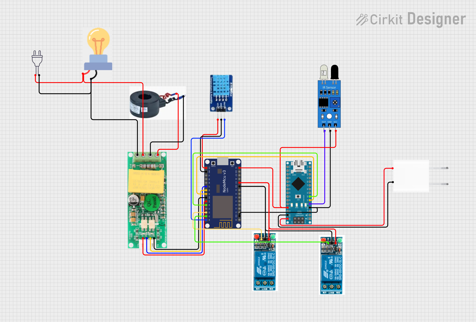
Circuit Documentation
Summary
The circuit in question appears to be a monitoring and control system that utilizes a NodeMCU V3 ESP8266 microcontroller as its central processing unit. The system is designed to interface with a PZEM004t module for electrical parameter measurements, a DHT11 sensor for temperature and humidity readings, an IR sensor for motion detection, and two 5V relays for controlling external devices such as a bulb. The Arduino Nano microcontroller is also included, potentially for additional control or processing tasks. A 5V adapter is used to power the Arduino Nano, while the NodeMCU V3 ESP8266 is powered via its Vin pin. The circuit is designed to operate with 220V power supply for the bulb and includes a current transformer (Ct) for current sensing.
Component List
NodeMCU V3 ESP8266
- Microcontroller with WiFi capability
- Pins: A0, GND, VU, S3, S2, S1, SC, S0, SK, 3V3, EN, RST, Vin, D0-D8, RX, TX
DHT11
- Temperature and humidity sensor
- Pins: DATA, GND, VCC
IR Sensor
- Infrared sensor for motion detection
- Pins: out, gnd, vcc
Ct (Current Transformer)
- Sensor for measuring alternating current (AC)
- Pins: P, N
Arduino Nano
- Compact microcontroller board based on the ATmega328P
- Pins: D0-D13, A0-A7, GND, VIN, 5V, 3V3, AREF, RESET
PZEM004t
- Module for measuring electrical parameters such as voltage, current, power, and energy
- Pins: VCC, RX, TX, GND, IN, OUT
Bulb
- Electrical load, presumably an incandescent or LED bulb
- Pins: GND, power
5V Adapter
- Power supply converting AC to 5V DC
- Pins: AC In 1, AC In 2, 5V, GND
5V Relay (x2)
- Electromechanical switch used for controlling high power devices
- Pins: Normally Open, Common terminal, Normally Closed, In, GND, VCC
Power 220V
- Main power supply for the circuit
- Pins: hot wire, neutral wire
Wiring Details
NodeMCU V3 ESP8266
- 3V3 connected to PZEM004t VCC, DHT11 VCC, and both 5V relays VCC
- GND connected to PZEM004t GND, DHT11 GND, IR sensor GND, both 5V relays GND, and Arduino Nano GND
- Vin connected to IR sensor VCC via Arduino Nano 5V
- D0 connected to DHT11 DATA
- D1 connected to 5V relay In (first relay)
- D2 connected to 5V relay In (second relay)
- D4 connected to Arduino Nano D4
- D5 connected to Arduino Nano D3
- D6 connected to PZEM004t TX
- D7 connected to PZEM004t RX
DHT11
- DATA connected to NodeMCU V3 ESP8266 D0
- GND connected to NodeMCU V3 ESP8266 GND
- VCC connected to NodeMCU V3 ESP8266 3V3
IR Sensor
- out connected to Arduino Nano D2
- gnd connected to NodeMCU V3 ESP8266 GND
- vcc connected to NodeMCU V3 ESP8266 Vin via Arduino Nano 5V
Ct (Current Transformer)
- N connected to PZEM004t IN
- P connected to PZEM004t OUT
Arduino Nano
- GND connected to IR sensor GND and 5V Adapter GND
- VIN connected to 5V Adapter 5V
- D2 connected to IR sensor out
- D3 connected to NodeMCU V3 ESP8266 D5
- D4 connected to NodeMCU V3 ESP8266 D4
PZEM004t
- VCC connected to NodeMCU V3 ESP8266 3V3
- RX connected to NodeMCU V3 ESP8266 D7
- TX connected to NodeMCU V3 ESP8266 D6
- GND connected to NodeMCU V3 ESP8266 GND
- IN connected to bulb power and Ct N
- OUT connected to bulb GND and Ct P
Bulb
- power connected to Power 220V hot wire and PZEM004t IN
- GND connected to Power 220V neutral wire and PZEM004t OUT
5V Adapter
- 5V connected to Arduino Nano VIN
- GND connected to Arduino Nano GND
5V Relay (x2)
- In connected to NodeMCU V3 ESP8266 D1 (first relay) and D2 (second relay)
- GND connected to NodeMCU V3 ESP8266 GND
- VCC connected to NodeMCU V3 ESP8266 3V3
Power 220V
- hot wire connected to bulb power
- neutral wire connected to bulb GND
Documented Code
Arduino Nano Code (Instance ID: 908f2f95-eb48-4b68-9f2b-54f4585eeb6f)
void setup() {
  // put your setup code here, to run once:

}

void loop() {
  // put your main code here, to run repeatedly:

}
Note: The provided code for the Arduino Nano is a template with no specific functionality. It will need to be populated with the logic required for the intended operation of the circuit.