Arduino-Controlled Audio Player with Real-Time Clock and Amplification

Circuit Documentation
Summary
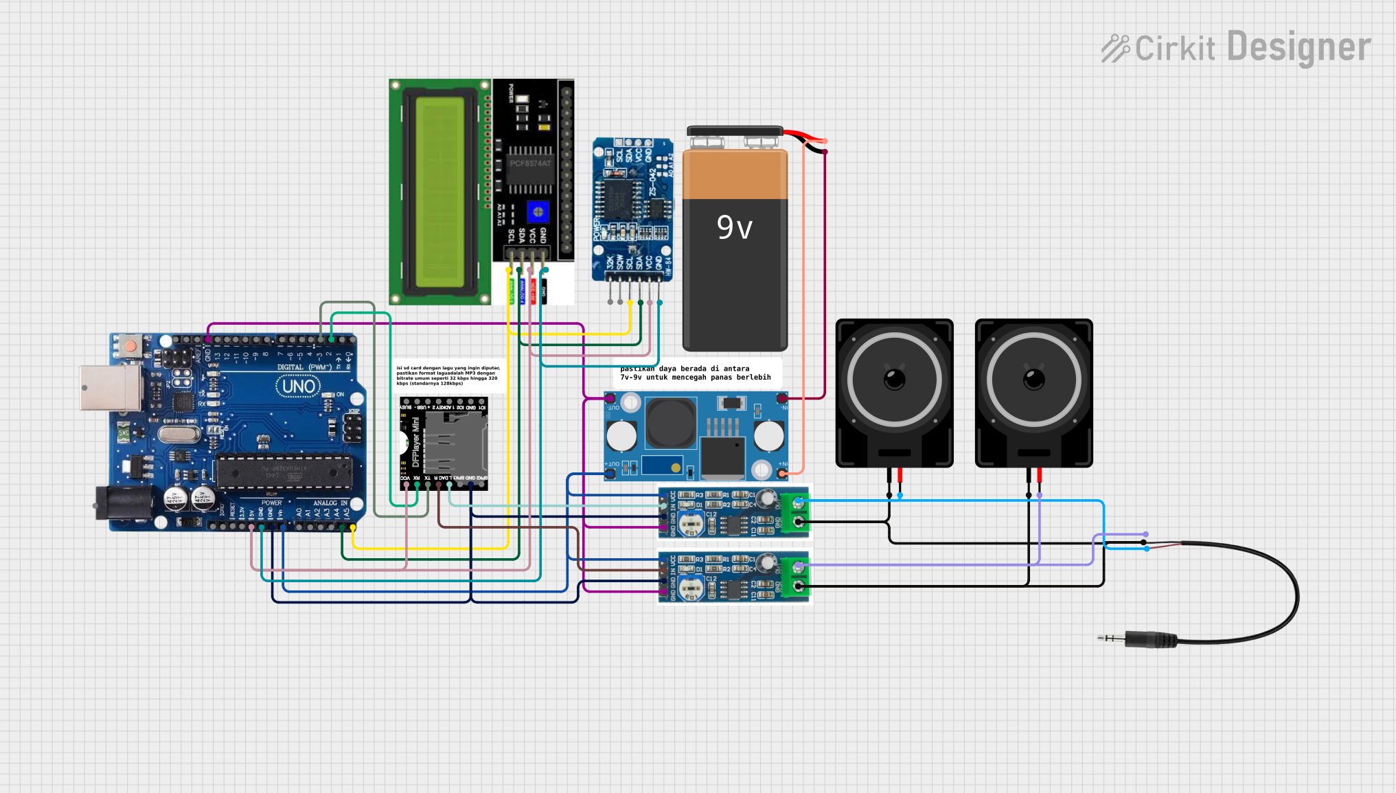
This circuit integrates various components to perform a set of functions centered around audio playback and display interfacing. The core of the circuit is an Arduino Uno R3, which controls an RTC DS3231 for real-time clock capabilities, an LM2596 Step Down Module for voltage regulation, a DFPlayer MINI for audio file playback, and an LCD I2C Display for user interface. The audio output from the DFPlayer MINI is amplified by two LM386 audio amplifier modules, each driving a loudspeaker. Additionally, a 3.5mm Audio Jack is included for external audio output. The circuit is powered by a 9V Battery connected through the LM2596 Step Down Module.
Component List
- Arduino Uno R3: A microcontroller board based on the ATmega328P, with digital and analog I/O pins.
- RTC DS3231: A real-time clock module for timekeeping.
- LM2596 Step Down Module: A voltage regulator module that steps down input voltage to a lower output voltage.
- DFPlayer MINI: A small and low-cost MP3 module that can directly play MP3 files.
- 9V Battery: Provides power to the circuit.
- LCD I2C Display: An alphanumeric liquid crystal display with an I2C interface.
- LM386 Audio Amplifier Module: An audio amplifier module for driving speakers.
- Loudspeaker: An electroacoustic transducer that converts an electrical audio signal into a corresponding sound.
- 3.5mm Audio Jack 3 Pin: A common audio connector for headphones and auxiliary audio connections.
Wiring Details
Arduino Uno R3
- VIN: Connected to the output of the LM2596 Step Down Module.
- GND: Common ground with LM386 audio amplifier modules, DFPlayer MINI, and RTC DS3231.
- 5V: Powers the RTC DS3231, LCD I2C Display, and DFPlayer MINI.
- A4/SDA, A5/SCL: I2C communication with RTC DS3231 and LCD I2C Display.
- Digital Pin 2: Connected to the RX pin of the DFPlayer MINI.
- Digital Pin 3: Connected to the TX pin of the DFPlayer MINI.
RTC DS3231
- VCC: Powered by the Arduino's 5V output.
- GND: Common ground with Arduino Uno R3.
- SCL, SDA: I2C communication with Arduino Uno R3.
LM2596 Step Down Module
- IN+: Connected to the positive terminal of the 9V Battery.
- IN-: Connected to the negative terminal of the 9V Battery.
- OUT+: Provides power to the Arduino Uno R3 and both LM386 audio amplifier modules.
- OUT-: Common ground with Arduino Uno R3 and both LM386 audio amplifier modules.
DFPlayer MINI
- VCC: Powered by the Arduino's 5V output.
- GND: Common ground with Arduino Uno R3.
- RX: Connected to Digital Pin 3 of the Arduino Uno R3.
- TX: Connected to Digital Pin 2 of the Arduino Uno R3.
- DAC_L, DAC_R: Audio output connected to the input of the LM386 audio amplifier modules.
LCD I2C Display
- VCC: Powered by the Arduino's 5V output.
- GND: Common ground with Arduino Uno R3.
- SDA, SCL: I2C communication with Arduino Uno R3.
LM386 Audio Amplifier Module
- VCC: Powered by the output of the LM2596 Step Down Module.
- GND: Common ground with Arduino Uno R3.
- IN: Audio input from the DFPlayer MINI.
- OUT: Connected to the Loudspeaker and optionally to the 3.5mm Audio Jack.
Loudspeaker
- pin1: Connected to the common ground with Arduino Uno R3.
- pin2: Connected to the output of the corresponding LM386 audio amplifier module.
3.5mm Audio Jack 3 Pin
- L: Connected to the output of one LM386 audio amplifier module.
- R: Connected to the output of the other LM386 audio amplifier module.
- GND: Common ground with Arduino Uno R3.
Documented Code
There is no code provided for the microcontrollers in the circuit. The functionality of the Arduino Uno R3 would typically be defined by the embedded code, which would control the interactions between the connected components such as the RTC, LCD display, and DFPlayer MINI. Without the code, the specific behavior of the circuit cannot be documented.