
Circuit Documentation
Summary
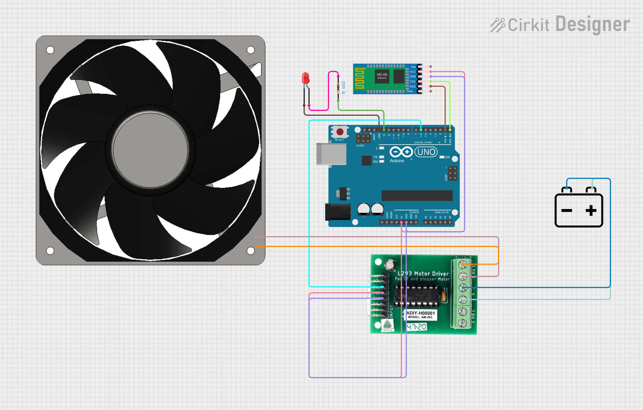
The circuit in question is designed to control a 12V fan using an Arduino UNO microcontroller, with the capability to communicate via Bluetooth through an HC-05 module. The fan is driven by an L293 motor driver, which is powered by a 12V battery. The circuit also includes a red LED with a series resistor to indicate operational status or for debugging purposes.
Component List
Arduino UNO
- Microcontroller board based on the ATmega328P
- It has 14 digital input/output pins, 6 analog inputs, a 16 MHz quartz crystal, a USB connection, a power jack, an ICSP header, and a reset button.
HC-05 Bluetooth Module
- A wireless communication module that allows for Bluetooth connectivity
- It has pins for Key, VCC, TXD, RXD, State, and GND.
LED: Two Pin (red)
- A simple red light-emitting diode
- It has an anode and a cathode pin for connection.
Resistor
- A passive two-terminal electrical component that implements electrical resistance as a circuit element
- This resistor has a value of 200 Ohms.
120 fan 12v
- A 12V fan used for cooling purposes
- It has a positive (12V+) and a ground (GND) connection.
12v Battery
- A power source for the circuit
- It has a positive (+) and a negative (-) terminal.
L293 Motor Driver
- A motor driver IC that allows DC motors to be driven from a microcontroller
- It has multiple pins for motor control, including enable pins, input pins, and power supply pins.
Wiring Details
Arduino UNO
- 5V connected to L293 motor driver VCC and HC-05 Bluetooth Module VCC
- GND connected to L293 motor driver GND, HC-05 Bluetooth Module GND, and LED cathode
- D13 connected to one side of the series resistor
- D6 connected to L293 motor driver EN_A
- D1 connected to HC-05 Bluetooth Module RXD
- D0 connected to HC-05 Bluetooth Module TXD
HC-05 Bluetooth Module
- VCC connected to Arduino UNO 5V
- GND connected to Arduino UNO GND
- TXD connected to Arduino UNO D0
- RXD connected to Arduino UNO D1
LED: Two Pin (red)
- Anode connected to one side of the series resistor
- Cathode connected to Arduino UNO GND
Resistor
- One side connected to Arduino UNO D13
- The other side connected to LED anode
120 fan 12v
- 12V+ connected to L293 motor driver MA1
- GND connected to L293 motor driver MA 2
12v Battery
- Positive (+) terminal connected to L293 motor driver +V
- Negative (-) terminal connected to L293 motor driver -V
L293 Motor Driver
- VCC connected to Arduino UNO 5V
- GND connected to Arduino UNO GND
- EN_A connected to Arduino UNO D6
- MA1 connected to 120 fan 12v 12V+
- MA 2 connected to 120 fan 12v GND
- +V connected to 12v Battery positive (+) terminal
- -V connected to 12v Battery negative (-) terminal
Documented Code
Arduino UNO Code (sketch.ino)
void setup() {
  // put your setup code here, to run once:

}

void loop() {
  // put your main code here, to run repeatedly:

}
Note: The provided code is a template and does not contain any functional code to control the circuit components. It needs to be populated with the appropriate setup and loop code to manage the Bluetooth communication and motor driver control.