
Arduino-Based Health Monitoring System with GSM Alert and I2C LCD Display
View and Edit Project In Cirkit Designer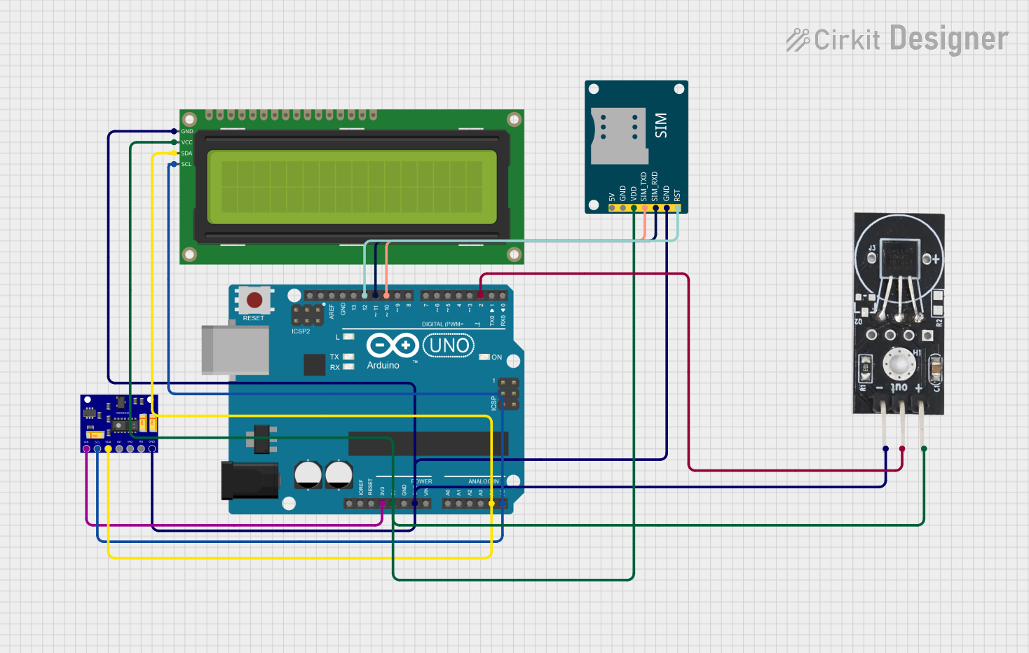
Circuit Documentation
Summary
This circuit is designed to monitor heart rate, blood oxygen levels (SpO2), and temperature, and display the readings on a 16x2 I2C LCD. Additionally, it can send alert messages via a SIM800L GSM module if certain thresholds are exceeded. The circuit uses an Arduino UNO as the main microcontroller, interfacing with a MAX30102 heart rate and oxygen sensor, a DS18B20 temperature sensor, a 16x2 I2C LCD, and a SIM800L GSM module.
Component List
Arduino UNO
- Description: Main microcontroller used to control the circuit.
- Pins: UNUSED, IOREF, Reset, 3.3V, 5V, GND, Vin, A0, A1, A2, A3, A4, A5, SCL, SDA, AREF, D13, D12, D11, D10, D9, D8, D7, D6, D5, D4, D3, D2, D1, D0
MAX30102 Heart Rate and Oxygen Sensor
- Description: Sensor used to measure heart rate and blood oxygen levels.
- Pins: VIN, SCL, SDA, INT, IRQ, RD, GND
DS18B20 Temperature Sensor
- Description: Sensor used to measure temperature.
- Pins: GND, VCC, OUT
16x2 I2C LCD
- Description: Display used to show heart rate, SpO2, and temperature readings.
- Pins: GND, VCC, SDA, SCL
SIM800L GSM Module
- Description: Module used to send alert messages via GSM.
- Pins: 5V, GND, VDD, SIM_TXD, SIM_RXD, RST
Wiring Details
Arduino UNO
- 3.3V connected to VIN of MAX30102 Heart Rate and Oxygen Sensor
- 5V connected to VCC of DS18B20 Temperature Sensor, VDD of SIM800L GSM Module, and VCC of 16x2 I2C LCD
- GND connected to GND of DS18B20 Temperature Sensor, GND of SIM800L GSM Module, GND of 16x2 I2C LCD, and GND of MAX30102 Heart Rate and Oxygen Sensor
- A4 connected to SDA of 16x2 I2C LCD and SDA of MAX30102 Heart Rate and Oxygen Sensor
- A5 connected to SCL of 16x2 I2C LCD and SCL of MAX30102 Heart Rate and Oxygen Sensor
- D2 connected to OUT of DS18B20 Temperature Sensor
- D10 connected to SIM_TXD of SIM800L GSM Module
- D11 connected to SIM_RXD of SIM800L GSM Module
- D12 connected to RST of SIM800L GSM Module
MAX30102 Heart Rate and Oxygen Sensor
- VIN connected to 3.3V of Arduino UNO
- GND connected to GND of Arduino UNO
- SDA connected to A4 of Arduino UNO
- SCL connected to A5 of Arduino UNO
DS18B20 Temperature Sensor
- VCC connected to 5V of Arduino UNO
- GND connected to GND of Arduino UNO
- OUT connected to D2 of Arduino UNO
16x2 I2C LCD
- VCC connected to 5V of Arduino UNO
- GND connected to GND of Arduino UNO
- SDA connected to A4 of Arduino UNO
- SCL connected to A5 of Arduino UNO
SIM800L GSM Module
- VDD connected to 5V of Arduino UNO
- GND connected to GND of Arduino UNO
- SIM_TXD connected to D10 of Arduino UNO
- SIM_RXD connected to D11 of Arduino UNO
- RST connected to D12 of Arduino UNO
Code Documentation
#include <Wire.h>
#include <LiquidCrystal_I2C.h>
#include <MAX30105.h>
#include <OneWire.h>
#include <DallasTemperature.h>
#include <SoftwareSerial.h>

// LCD setup
LiquidCrystal_I2C lcd(0x27, 16, 2);

// MAX30102 setup
MAX30105 particleSensor;

// DS18B20 setup
#define ONE_WIRE_BUS 2
OneWire oneWire(ONE_WIRE_BUS);
DallasTemperature sensors(&oneWire);

// SIM800L setup
SoftwareSerial sim800l(10, 11); // RX, TX

void setup() {
  // Initialize serial communication
  Serial.begin(9600);
  sim800l.begin(9600);

  // Initialize LCD
  lcd.begin();
  lcd.backlight();

  // Initialize MAX30102
  if (!particleSensor.begin(Wire, I2C_SPEED_FAST)) {
    Serial.println("MAX30102 was not found. Please check wiring/power.");
    while (1);
  }
  particleSensor.setup();

  // Initialize DS18B20
  sensors.begin();

  // Initialize SIM800L
  sim800l.println("AT");
  delay(1000);
  sim800l.println("AT+CMGF=1"); // Set SMS to text mode
  delay(1000);
}

void loop() {
  // Read data from MAX30102
  long irValue = particleSensor.getIR();
  long redValue = particleSensor.getRed();
  float heartRate = calculateHeartRate(irValue, redValue);
  float spo2 = calculateSpO2(irValue, redValue);

  // Read temperature from DS18B20
  sensors.requestTemperatures();
  float temperature = sensors.getTempCByIndex(0);

  // Display data on LCD
  lcd.clear();
  lcd.setCursor(0, 0);
  lcd.print("HR: ");
  lcd.print(heartRate);
  lcd.print(" bpm");
  lcd.setCursor(0, 1);
  lcd.print("SpO2: ");
  lcd.print(spo2);
  lcd.print(" %");
  delay(2000);
  lcd.clear();
  lcd.setCursor(0, 0);
  lcd.print("Temp: ");
  lcd.print(temperature);
  lcd.print(" C");

  // Send alert message if needed
  if (heartRate > 100 || spo2 < 95 || temperature > 37.5) {
    sendAlertMessage(heartRate, spo2, temperature);
  }

  delay(5000);
}

float calculateHeartRate(long irValue, long redValue) {
  // Placeholder function for heart rate calculation
  return (irValue + redValue) / 1000.0;
}

float calculateSpO2(long irValue, long redValue) {
  // Placeholder function for SpO2 calculation
  return (irValue + redValue) / 1000.0;
}

void sendAlertMessage(float heartRate, float spo2, float temperature) {
  sim800l.println("AT+CMGS=\"+1234567890\""); // Replace with your phone number
  delay(1000);
  sim800l.print("Alert! HR: ");
  sim800l.print(heartRate);
  sim800l.print(" bpm, SpO2: ");
  sim800l.print(spo2);
  sim800l.print(" %, Temp: ");
  sim800l.print(temperature);
  sim800l.print(" C");
  sim800l.write(26); // ASCII code for CTRL+Z to send the message
  delay(1000);
}
This code initializes the sensors and the LCD, reads data from the sensors, displays the data on the LCD, and sends an alert message via the SIM800L GSM module if the readings exceed certain thresholds. The calculateHeartRate and calculateSpO2 functions are placeholders and should be replaced with actual algorithms for calculating heart rate and SpO2.