
Circuit Documentation
Summary
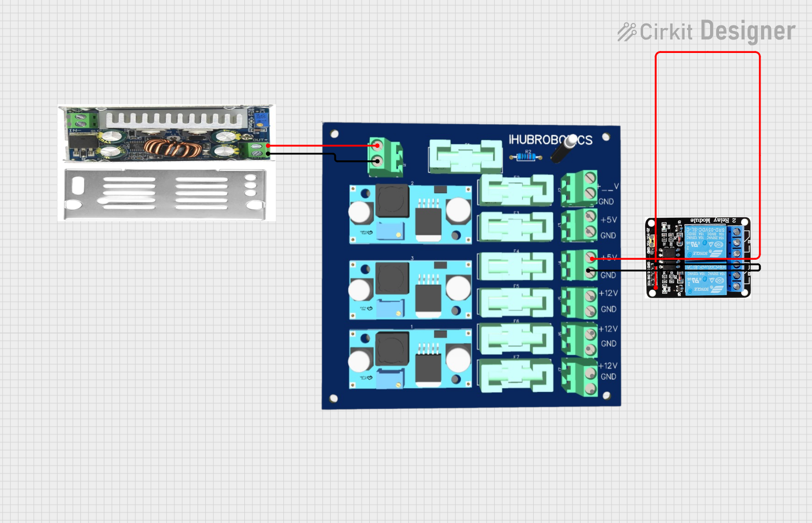
This document provides a detailed overview of a circuit consisting of a power module, a DC-DC converter, and a 5V 2-relay module. The circuit is designed to manage power distribution and control relay operations. The document includes a component list, wiring details, and code documentation.
Component List
Power Module 6 Channel
- Description: A power module that provides multiple voltage outputs.
- Pins: In +ve, In -ve, 5v +ve, 12v +ve, 5v Gnd, 12v Gnd
5V 2-Relay JD-VCC
- Description: A relay module that operates at 5V and can control two separate circuits.
- Pins: JD-VCC, VCC, GND, IN1, IN2, NO, COM, NC
DC-DC Converter
- Description: A converter that steps down or steps up voltage as required.
- Pins: Out +ve, Out -ve, In +ve, In -ve
Wiring Details
Power Module 6 Channel
- In +ve: Connected to Out +ve of DC-DC Converter
- In -ve: Connected to Out -ve of DC-DC Converter
- 5v +ve: Connected to VCC of 5V 2-Relay JD-VCC
- 5v Gnd: Connected to GND of 5V 2-Relay JD-VCC
5V 2-Relay JD-VCC
- VCC: Connected to 5v +ve of Power Module 6 Channel
- GND: Connected to 5v Gnd of Power Module 6 Channel
DC-DC Converter
- Out +ve: Connected to In +ve of Power Module 6 Channel
- Out -ve: Connected to In -ve of Power Module 6 Channel
Code Documentation
There is no code provided for this circuit.
This document provides a comprehensive overview of the circuit, including the components used and their interconnections. The wiring details ensure that each component is correctly connected to achieve the desired functionality.