
Circuit Documentation
Summary of the Circuit
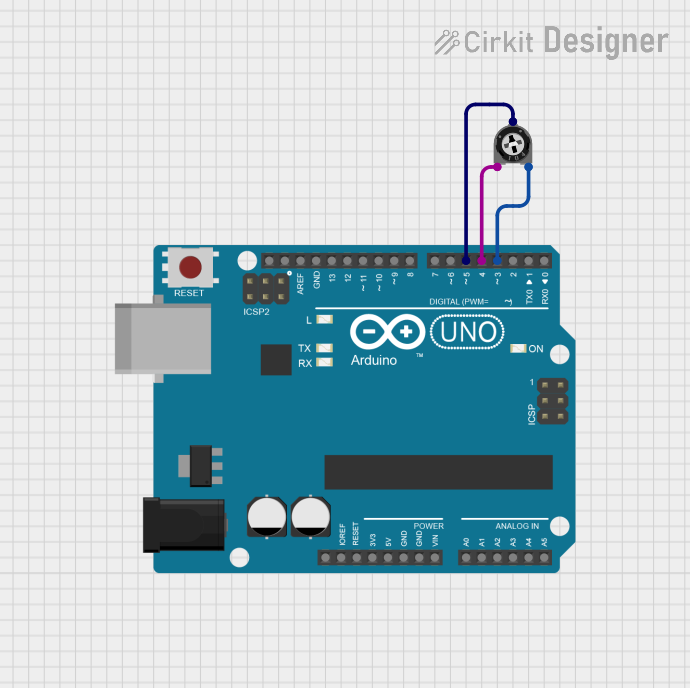
This circuit consists of an Arduino UNO microcontroller and a trimmer potentiometer. The Arduino UNO is used as the central processing unit, controlling the voltage levels on its digital pins to interface with the potentiometer. The trimmer potentiometer is connected to the Arduino and is likely used to provide analog input to the microcontroller based on its position.
Component List
Arduino UNO
- Description: A microcontroller board based on the ATmega328P.
- Pins: UNUSED, IOREF, Reset, 3.3V, 5V, GND, Vin, A0-A5, SCL, SDA, AREF, D0-D13.
- Purpose: Acts as the central processing unit of the circuit, controlling the logic and interfacing with other components.
Trimmer Potentiometer
- Description: A variable resistor with a knob or slider for adjusting resistance.
- Pins: leg1, wiper, leg2.
- Properties: Resistance - 10,000 Ohms.
- Purpose: Provides a variable voltage input to the Arduino UNO, which can be read from an analog input pin.
Wiring Details
Arduino UNO
- D4: Connected to leg1 of the Trimmer Potentiometer.
- D5: Connected to the wiper of the Trimmer Potentiometer.
- D3: Connected to leg2 of the Trimmer Potentiometer.
Trimmer Potentiometer
- leg1: Connected to D4 on the Arduino UNO.
- wiper: Connected to D5 on the Arduino UNO.
- leg2: Connected to D3 on the Arduino UNO.
Documented Code
// sketch.ino for Arduino UNO

void setup() {
  // Configure pin D4 as an output
  pinMode(4, OUTPUT);
  // Set pin D4 high
  digitalWrite(4, HIGH);

  // Configure pin D3 as an output
  pinMode(3, OUTPUT);
  // Set pin D3 low
  digitalWrite(3, LOW);
}

void loop() {
  // Main code loop, currently empty
}
File Name: sketch.ino
Description: This code configures digital pins D4 and D3 of the Arduino UNO as outputs. It sets D4 to a high voltage level and D3 to a low voltage level. The loop function is currently empty, indicating that the main program logic is yet to be implemented or is handled in an interrupt-driven manner.