
Raspberry Pi 4B Controlled E-Bike with GPS and Ultrasonic Sensors
View and Edit Project In Cirkit Designer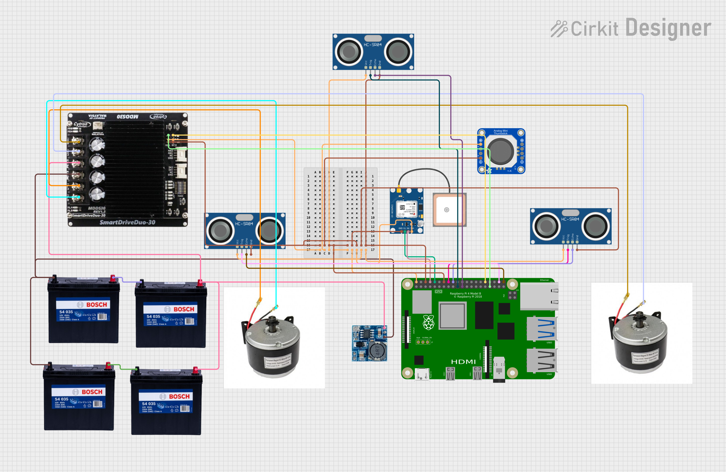
Circuit Documentation
Summary
This circuit integrates a Raspberry Pi 4B with various peripherals including a GPS module (GPS NEO 6M), multiple HC-SR04 ultrasonic sensors, an Adafruit Mini Analog Thumbstick, two 24V e-bike DC motors, and a Cytron motor driver (MDDS30). The system is powered by a series of 12V 200Ah batteries, and a step-down module is used to convert the voltage to appropriate levels for the components requiring 5V. The Raspberry Pi 4B serves as the central processing unit, interfacing with the GPS module for location tracking and controlling the ultrasonic sensors for distance measurement. The motor driver is responsible for controlling the e-bike motors based on input from the Raspberry Pi 4B.
Component List
Raspberry Pi 4B
- Microcontroller and central processing unit of the circuit.
- Provides GPIO pins for interfacing with sensors, motor driver, and other peripherals.
GPS NEO 6M
- GPS module for location tracking.
- Communicates with the Raspberry Pi via serial connection.
HC-SR04 Ultrasonic Sensor
- Ultrasonic sensors for distance measurement.
- Multiple instances are used for multi-directional distance sensing.
24V e-bike DC Motor
- Actuators for the e-bike.
- Controlled by the Cytron motor driver.
12V 200Ah Battery
- Power source for the circuit.
- Multiple batteries are connected to provide sufficient power and voltage levels.
MDDS30 A Cytron Motor Driver
- Motor driver for controlling the e-bike DC motors.
- Receives control signals from the Raspberry Pi.
Step-down Module
- Voltage regulator to step down the voltage from 24V to 5V for components that require lower voltage.
Adafruit Mini Analog Thumbstick
- Analog input device to provide user control.
- Interfaced with the Raspberry Pi for manual control inputs.
Wiring Details
Raspberry Pi 4B
5Vconnected to the 5V power rail.GNDconnected to the ground rail.GPIO14(TX) connected toRXon GPS NEO 6M.GPIO15(RX) connected toTXon GPS NEO 6M.GPIO23,GPIO24connected toTRIGandECHOon one HC-SR04 sensor.GPIO10,GPIO9connected toTRIGandECHOon another HC-SR04 sensor.GPIO20,GPIO21connected toTRIGandECHOon a third HC-SR04 sensor.GPIO12,GPIO13connected toSIG1andSIG2on the Cytron motor driver.
GPS NEO 6M
VCCconnected to the 5V power rail.GNDconnected to the ground rail.RXconnected toGPIO14(TX) on Raspberry Pi.TXconnected toGPIO15(RX) on Raspberry Pi.
HC-SR04 Ultrasonic Sensor
VCCconnected to the 5V power rail.GNDconnected to the ground rail.TRIGandECHOconnected to designated GPIO pins on Raspberry Pi.
24V e-bike DC Motor
vccandgndconnected toMLA/MLBandMRA/MRBon the Cytron motor driver.
12V 200Ah Battery
GNDconnected to the ground rail.12Vconnected to the 24V power rail and the step-down module.
MDDS30 A Cytron Motor Driver
5Vconnected to the 5V power rail.GNDconnected to the ground rail.SIG1,SIG2connected toGPIO12,GPIO13on Raspberry Pi.MLA,MLB,MRA,MRBconnected to the respective motor terminals.VB+,VB-connected to the 24V power rail and ground rail respectively.
Step-down Module
24v IN+connected to the 24V power rail.GNDconnected to the ground rail.5v OUT+,5v OUT-connected to the 5V power rail and ground rail respectively.
Adafruit Mini Analog Thumbstick
VCCconnected to the 5V power rail.GNDconnected to the ground rail.YOUT,XOUTconnected to analog input pins on Raspberry Pi (not specified in the net list).
Documented Code
Raspberry Pi 4B Code (sketch.ino)
void setup() {
  // put your setup code here, to run once:

}

void loop() {
  // put your main code here, to run repeatedly:

}
Step-down Module Code (sketch.ino)
void setup() {
  // put your setup code here, to run once:

}

void loop() {
  // put your main code here, to run repeatedly:

}
(Note: The provided code for both the Raspberry Pi 4B and the Step-down Module is a template with no specific functionality. Additional code is required to control the peripherals and implement the desired behavior of the circuit.)