Cirkit Designer
Your all-in-one circuit design IDE
Home /
Project Documentation
Arduino-Based RGB Color Detection System with OLED and LCD Displays
Circuit Documentation
Summary
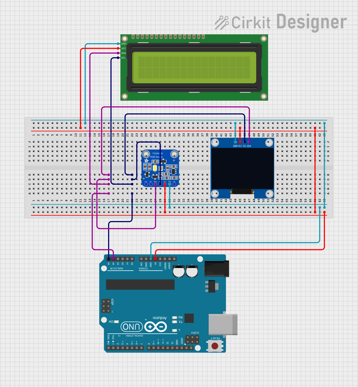
This circuit involves an Arduino UNO microcontroller interfacing with a 128x64 OLED Display, a 16x2 I2C LCD, and an Adafruit TCS34725 RGB Color Sensor. The circuit is designed to read color data from the RGB sensor and display the results on both the OLED and LCD screens.
Component List
128x64 OLED Display (I2C IIC SPI Serial)
- Description: A monochrome 128x64 OLED display module that communicates via I2C.
- Pins: GND, SDA, SCL, VCC
Adafruit TCS34725 RGB Color Sensor
- Description: A color sensor that can detect RGB values and has an I2C interface.
- Pins: LED_EN, INT, SDA, SCL, +3V3, GND, VIN
Arduino UNO
- Description: A microcontroller board based on the ATmega328P, featuring 14 digital input/output pins, 6 analog inputs, and various communication interfaces.
- Pins: UNUSED, IOREF, Reset, 3.3V, 5V, GND, Vin, A0, A1, A2, A3, A4, A5, SCL, SDA, AREF, D13, D12, D11, D10, D9, D8, D7, D6, D5, D4, D3, D2, D1, D0
16x2 I2C LCD
- Description: A 16x2 character LCD display with an I2C interface.
- Pins: GND, VCC, SDA, SCL
Wiring Details
128x64 OLED Display (I2C IIC SPI Serial)
- GND: Connected to Arduino UNO GND
- SDA: Connected to Arduino UNO A4
- SCL: Connected to Arduino UNO A5
- VCC: Connected to Arduino UNO 5V
Adafruit TCS34725 RGB Color Sensor
- LED_EN: Not connected
- INT: Not connected
- SDA: Connected to Arduino UNO A4
- SCL: Connected to Arduino UNO A5
- +3V3: Connected to Arduino UNO 5V
- GND: Connected to Arduino UNO GND
- VIN: Not connected
Arduino UNO
- A4: Connected to SDA of OLED Display, RGB Color Sensor, and I2C LCD
- A5: Connected to SCL of OLED Display, RGB Color Sensor, and I2C LCD
- 5V: Connected to VCC of OLED Display, RGB Color Sensor, and I2C LCD
- GND: Connected to GND of OLED Display, RGB Color Sensor, and I2C LCD
16x2 I2C LCD
- GND: Connected to Arduino UNO GND
- VCC: Connected to Arduino UNO 5V
- SDA: Connected to Arduino UNO A4
- SCL: Connected to Arduino UNO A5
Code Documentation
#include <Wire.h>
#include "Adafruit_TCS34725.h"
#include <LiquidCrystal_I2C.h>
#include <Adafruit_GFX.h>
#include <Adafruit_SSD1306.h>

#define WIDTH 128
#define HEIGHT 64

LiquidCrystal_I2C lcd(0x27, 20, 4);
Adafruit_TCS34725 tcs = Adafruit_TCS34725(TCS34725_INTEGRATIONTIME_50MS, TCS34725_GAIN_4X);
Adafruit_SSD1306 display(WIDTH, HEIGHT, &Wire, 1);

void setup(void) {
  Serial.begin(9600);
  if (tcs.begin()) {
    Serial.println("Found sensor");
  }
  else {
    Serial.println("No TCS34725 found ... check your connections");
    while (1);
  }

  lcd.init();
  lcd.clear();
  lcd.backlight();

  lcd.setCursor(0, 0);

  if(!display.begin(SSD1306_SWITCHCAPVCC, 0x3c)){
     Serial.println("OLED not found");
   }

  Serial.println("OLED FIND");
  display.clearDisplay();
  display.setTextColor(WHITE);
  display.setTextSize(1);
  display.setCursor(0,28);
  display.println("hello");
  display.display();

  pinMode(A0, OUTPUT);
  digitalWrite(A0, HIGH);
}

void loop(void) {
  uint16_t red, green, blue, c;
  tcs.getRawData(&red, &green, &blue, &c); // Get raw data from the color sensor

  // Map the raw data to a usable range
  int r = map(red, 0, 21504, 0, 1025);
  int g = map(green, 0, 21504, 0, 1025);
  int b = map(blue, 0, 21504, 0, 1025);

  Serial.print("R: "); Serial.print(r, DEC); Serial.print(" ");
  Serial.print("G: "); Serial.print(g, DEC); Serial.print(" ");
  Serial.print("B: "); Serial.print(b, DEC); Serial.print(" ");
  Serial.print("C: "); Serial.print(c, DEC); Serial.print(" ");
  Serial.println(" ");

  if(r > g && r > b){
    lcd.clear();
    lcd.setCursor(0, 0);
    lcd.print("RED");
  }
  else if(g > r && g > b){
    lcd.clear();
    lcd.setCursor(0, 0);
    lcd.print("GREEN");
  }
  else if(b > r && b > g){
    lcd.clear();
    lcd.setCursor(0, 0);
    lcd.print("BLUE");
  }
  else if(g == b && r == b){
    lcd.clear();
    lcd.setCursor(0, 0);
    lcd.print("ALL");
  }
  else if(g == b && g > r){
    lcd.clear();
    lcd.setCursor(0, 0);
    lcd.print("GREEN & BLUE");
  }
  else if(g == r && g > b){
    lcd.clear();
    lcd.setCursor(0, 0);
    lcd.print("GREEN & RED");
  }
  else if(r == b && r > g){
    lcd.clear();
    lcd.setCursor(0, 0);
    lcd.print("RED & BLUE");
  }
  else{
    lcd.clear();
    lcd.setCursor(0, 0);
    lcd.print("else");
  }

  display.clearDisplay();

  // Draw red bar
  display.setTextSize(1);
  display.setTextColor(SSD1306_WHITE);
  display.setCursor(0, 0);
  display.print("R:");
  display.fillRect(20, 0, r, 10, SSD1306_WHITE);

  // Draw green bar
  display.setCursor(0, 15);
  display.print("G:");
  display.fillRect(20, 15, g, 10, SSD1306_WHITE);

  // Draw blue bar
  display.setCursor(0, 30);
  display.print("B:");
  display.fillRect(20, 30, b, 10, SSD1306_WHITE);

  display.display();

  delay(500);
}
This code initializes the RGB color sensor, the OLED display, and the LCD display. It reads color data from the sensor and displays the results on both the OLED and LCD screens. The color data is also printed to the serial monitor.