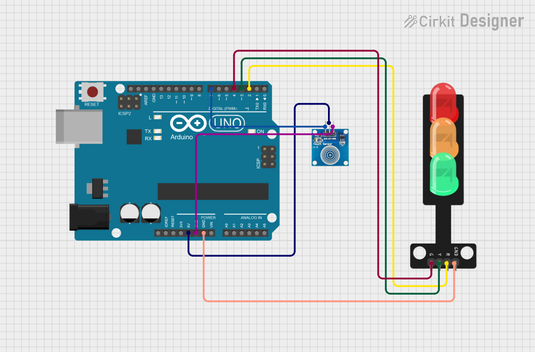
Arduino UNO Touch-Activated Traffic Light Controller

Circuit Documentation
Summary of the Circuit
This circuit is designed to control a traffic light system using an Arduino UNO microcontroller and a touch sensor. The system operates in a cycle where the state of the traffic light changes upon each touch sensor activation. The cycle progresses from red to yellow to green and then turns off all lights before repeating. The Arduino UNO reads the state of the touch sensor and controls the traffic light LEDs accordingly.
Component List
Touch Sensor
- Pins: IO, VCC, GND
- Description: A sensor that detects touch or proximity to trigger an event.
- Purpose: To provide a user interface for changing the state of the traffic light.
Arduino UNO
- Pins: UNUSED, IOREF, Reset, 3.3V, 5V, GND, Vin, A0-A5, SCL, SDA, AREF, D0-D13
- Description: A microcontroller board based on the ATmega328P.
- Purpose: To serve as the central processing unit of the circuit, reading sensor inputs and controlling the traffic light LEDs.
Traffic Light
- Pins: Green, Yellow, Red, GND
- Description: A set of LEDs representing a traffic light.
- Purpose: To visually represent the traffic light state as controlled by the Arduino UNO.
Wiring Details
Touch Sensor
- IO: Connected to Arduino UNO pin D7
- VCC: Connected to Arduino UNO pin 5V
- GND: Connected to Arduino UNO pin GND
Arduino UNO
- D7: Connected to Touch Sensor IO
- 5V: Power supply to Touch Sensor VCC
- GND: Common ground for Touch Sensor and Traffic Light
- D4: Connected to Traffic Light Green
- D3: Connected to Traffic Light Yellow
- D2: Connected to Traffic Light Red
Traffic Light
- Green: Controlled by Arduino UNO pin D4
- Yellow: Controlled by Arduino UNO pin D3
- Red: Controlled by Arduino UNO pin D2
- GND: Connected to Arduino UNO pin GND
Documented Code
/*
 * This Arduino Sketch controls a traffic light system using a touch sensor.
 * When the touch sensor is pressed, the red LED turns on. On the next press,
 * the yellow LED turns on. On the next press, the green LED turns on. On the
 * next press, all LEDs turn off. This cycle repeats with each subsequent press.
 */

const int touchPin = 7; // Pin connected to touch sensor
const int redPin = 2;   // Pin connected to red LED
const int yellowPin = 3; // Pin connected to yellow LED
const int greenPin = 4; // Pin connected to green LED

int touchState = 0;     // Current state of the touch sensor
int lastTouchState = 0; // Previous state of the touch sensor
int ledState = 0;       // State of the LEDs (0: all off, 1: red, 2: yellow, 3: green)

void setup() {
  pinMode(touchPin, INPUT);
  pinMode(redPin, OUTPUT);
  pinMode(yellowPin, OUTPUT);
  pinMode(greenPin, OUTPUT);
  // Initialize all LEDs to off
  digitalWrite(redPin, LOW);
  digitalWrite(yellowPin, LOW);
  digitalWrite(greenPin, LOW);
}

void loop() {
  touchState = digitalRead(touchPin);
  // Check if the touch sensor state has changed
  if (touchState != lastTouchState) {
    if (touchState == HIGH) {
      // Cycle through LED states
      ledState = (ledState + 1) % 4;
      updateLEDs();
    }
    // Debounce delay
    delay(50);
  }
  lastTouchState = touchState;
}

void updateLEDs() {
  // Turn off all LEDs
  digitalWrite(redPin, LOW);
  digitalWrite(yellowPin, LOW);
  digitalWrite(greenPin, LOW);
  // Turn on the appropriate LED based on the current state
  switch (ledState) {
    case 1:
      digitalWrite(redPin, HIGH);
      break;
    case 2:
      digitalWrite(yellowPin, HIGH);
      break;
    case 3:
      digitalWrite(greenPin, HIGH);
      break;
  }
}
The code is written for the Arduino UNO microcontroller. It initializes the pins connected to the touch sensor and the traffic light LEDs. The loop function continuously reads the state of the touch sensor and updates the state of the LEDs accordingly. The updateLEDs function is responsible for turning on the appropriate LED based on the current state of the system.