
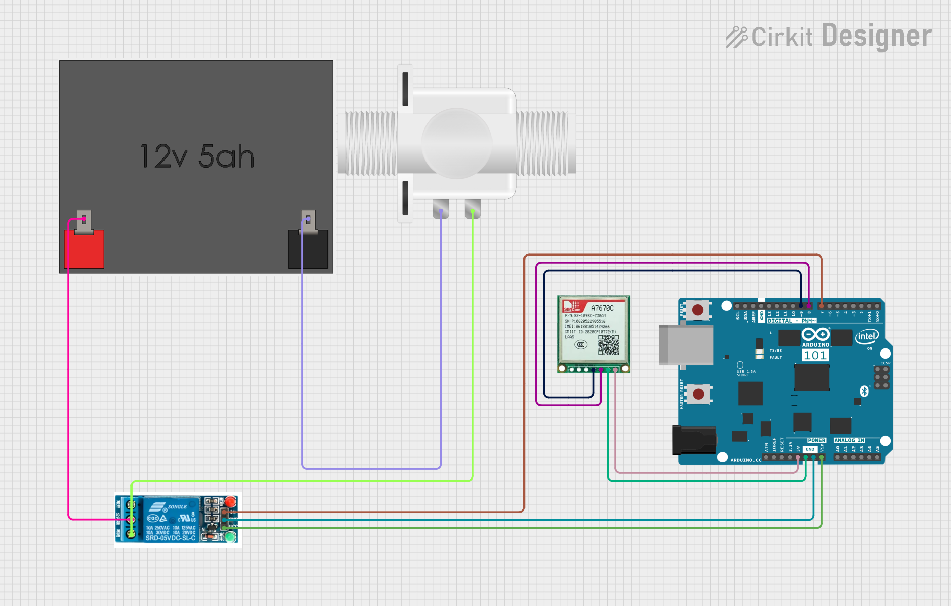
Circuit Documentation
Summary
This circuit interfaces an Arduino 101 with a GSM module (Sim A7670c) to control a solenoid valve via SMS commands. When an SMS with the text 'ON' is received, the Arduino will open the valve for 2 seconds, send a confirmation SMS, then close the valve and send another confirmation SMS. The circuit also includes a 5V relay to control the solenoid valve and is powered by a 12V 5Ah battery.
Component List
Arduino 101
- Description: Microcontroller board based on the Intel Curie module.
- Pins: A5/SCL, A4/SDA, AREF, GND, D13/SCK, D12/MISO, D11 PWM/MOSI, D10 PWM/SS, D9 PWM, D8, D7, D6 PWM, D5 PWM, D4, D3 PWM, D2, D1/TX, D0/RX, AIN, ioref, RESET, 3V3, 5V, VIN, A0, A1, A2, A3, ICSP MISO, ICSP SCK, ICSP MOSI
Sim A7670c
- Description: GSM module for sending and receiving SMS.
- Pins: Vin, Gnd, Tx, Rx
12V 5Ah Battery
- Description: Power source for the circuit.
- Pins: 12v +, 12v -
5V Relay
- Description: Relay module to control the solenoid valve.
- Pins: Normally Open, Common terminal, Normally Closed, In, GND, VCC
Plastic Solenoid Valve
- Description: Valve controlled by the relay to manage water flow.
- Pins: pin1, pin2
Wiring Details
Arduino 101
- D9 PWM connected to Rx of Sim A7670c
- D8 connected to Tx of Sim A7670c
- D7 connected to In of 5V Relay
- 5V connected to Vin of Sim A7670c
- GND connected to Gnd of Sim A7670c
- GND connected to GND of 5V Relay
- VIN connected to VCC of 5V Relay
Sim A7670c
- Rx connected to D9 PWM of Arduino 101
- Tx connected to D8 of Arduino 101
- Vin connected to 5V of Arduino 101
- Gnd connected to GND of Arduino 101
12V 5Ah Battery
- 12v + connected to Common terminal of 5V Relay
- 12v - connected to pin1 of Plastic Solenoid Valve
5V Relay
- In connected to D7 of Arduino 101
- GND connected to GND of Arduino 101
- VCC connected to VIN of Arduino 101
- Common terminal connected to 12v + of 12V 5Ah Battery
- Normally Closed connected to pin2 of Plastic Solenoid Valve
Plastic Solenoid Valve
- pin1 connected to 12v - of 12V 5Ah Battery
- pin2 connected to Normally Closed of 5V Relay
Code Documentation
/*
 * This Arduino sketch interfaces with a GSM module to control a solenoid valve.
 * When an SMS with the text 'ON' is received, the Arduino will open the valve
 * for 2 seconds, send a confirmation SMS, then close the valve and send another
 * confirmation SMS.
 */

#include <SoftwareSerial.h>

// Pin definitions
const int gsmRxPin = 9; // GSM module RX pin
const int gsmTxPin = 8; // GSM module TX pin
const int relayPin = 7; // Relay control pin

// Create a SoftwareSerial object for GSM communication
SoftwareSerial gsmSerial(gsmRxPin, gsmTxPin);

void setup() {
  // Initialize serial communication with GSM module
  gsmSerial.begin(9600);
  // Initialize serial communication with the computer
  Serial.begin(9600);
  // Set relay pin as output
  pinMode(relayPin, OUTPUT);
  // Ensure relay is off
  digitalWrite(relayPin, LOW);
}

void loop() {
  // Check if there is any data from the GSM module
  if (gsmSerial.available()) {
    String sms = gsmSerial.readString();
    // Check if the SMS contains the text 'ON'
    if (sms.indexOf("ON") >= 0) {
      // Open the solenoid valve
      digitalWrite(relayPin, HIGH);
      delay(2000); // Keep the valve open for 2 seconds
      // Close the solenoid valve
      digitalWrite(relayPin, LOW);
      // Send confirmation SMS
      sendSMS("Water opened");
      delay(1000); // Wait for a second
      sendSMS("Water stopped");
    }
  }
}

void sendSMS(String message) {
  gsmSerial.println("AT+CMGF=1"); // Set SMS mode to text
  delay(100);
  gsmSerial.println("AT+CMGS=\"+1234567890\""); // Replace with actual phone number
  delay(100);
  gsmSerial.print(message);
  delay(100);
  gsmSerial.write(26); // ASCII code for CTRL+Z to send the SMS
  delay(1000); // Wait for the SMS to be sent
}
This code initializes the GSM module and sets up the relay pin. It continuously checks for incoming SMS messages. If an SMS with the text 'ON' is received, it opens the solenoid valve for 2 seconds, sends a confirmation SMS, then closes the valve and sends another confirmation SMS.