
Circuit Documentation
Summary of the Circuit
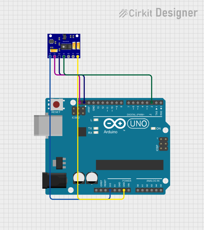
This circuit consists of an Arduino UNO microcontroller board interfaced with a MAX30102 Heart Rate and Oxygen Sensor. The Arduino UNO is responsible for controlling the sensor and processing the data it generates. The MAX30102 sensor is used to measure heart rate and blood oxygen levels, and it communicates with the Arduino UNO via the I2C protocol. The sensor's interrupt pin is connected to a digital pin on the Arduino to handle asynchronous events.
Component List
Arduino UNO
- Description: A microcontroller board based on the ATmega328P.
- Pins Used:
3.3V: Power supply to the MAX30102 sensor.GND: Ground reference for the circuit.SCL: I2C clock line for communication with the MAX30102 sensor.SDA: I2C data line for communication with the MAX30102 sensor.D2: Digital input for the interrupt signal from the MAX30102 sensor.
MAX30102 Heart Rate and Oxygen Sensor
- Description: An integrated pulse oximetry and heart-rate monitor sensor solution.
- Pins Used:
VIN: Power supply input (connected to 3.3V from Arduino UNO).GND: Ground reference for the circuit.SCL: I2C clock line (connected to Arduino UNO).SDA: I2C data line (connected to Arduino UNO).INT: Interrupt output (connected to Arduino UNO D2).
Wiring Details
Arduino UNO
3.3Vto MAX30102VINGNDto MAX30102GNDSCLto MAX30102SCLSDAto MAX30102SDAD2to MAX30102INT
MAX30102 Heart Rate and Oxygen Sensor
VINto Arduino UNO3.3VGNDto Arduino UNOGNDSCLto Arduino UNOSCLSDAto Arduino UNOSDAINTto Arduino UNOD2
Documented Code
Arduino UNO Code (sketch.ino)
void setup() {
  // put your setup code here, to run once:

}

void loop() {
  // put your main code here, to run repeatedly:

}
Note: The provided code is a template and does not include specific functionality for interacting with the MAX30102 sensor. Additional code is required to initialize the sensor, read data, and handle interrupts.