
Circuit Documentation
Summary of the Circuit
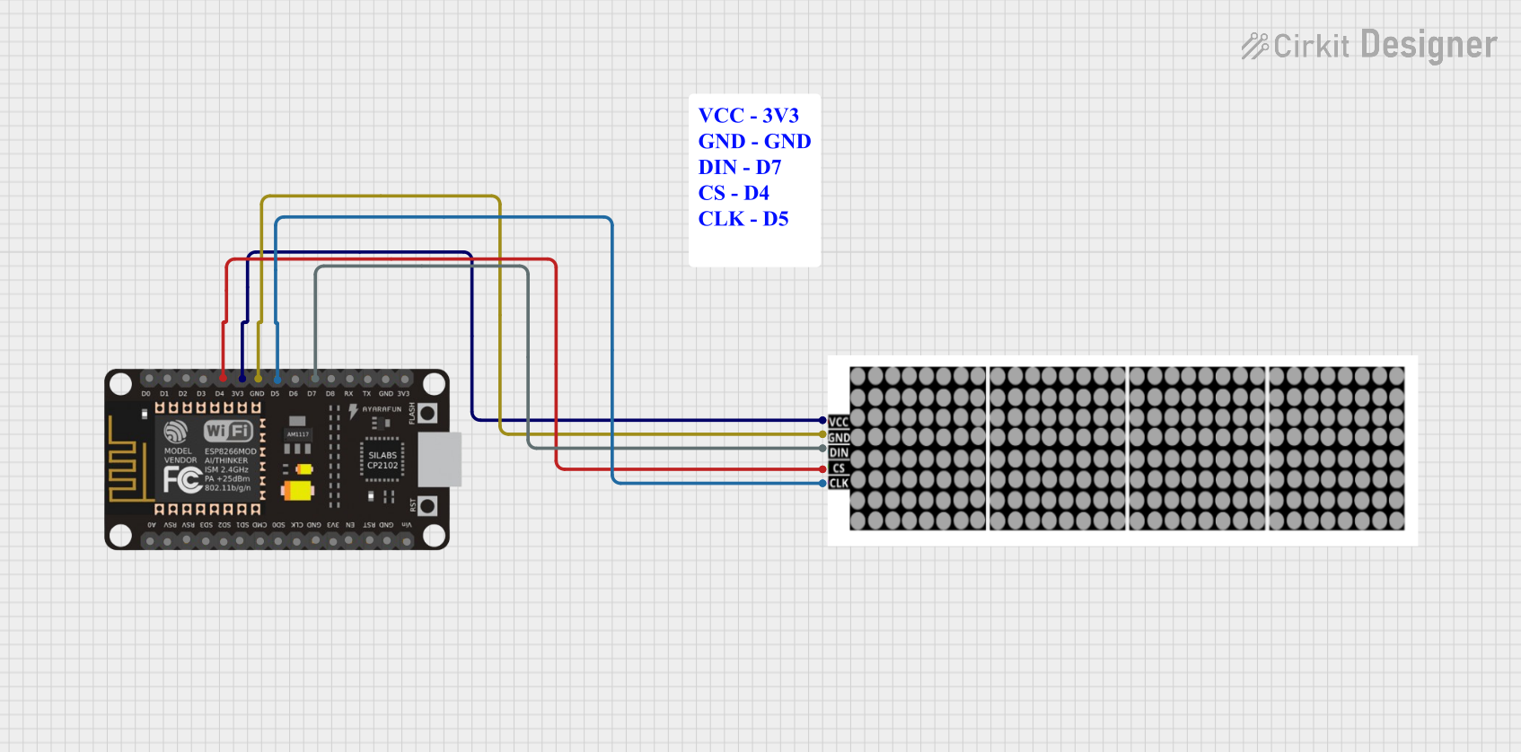
This circuit consists of an LED Dot Display module interfaced with an ESP8266 NodeMCU microcontroller. The LED Dot Display is powered by the 3.3V supply from the ESP8266 and shares a common ground. The data input, chip select, and clock signals for the LED Dot Display are controlled by digital pins on the ESP8266. This setup is typically used for displaying information or patterns on the LED Dot Display, which can be programmed via the ESP8266 microcontroller.
Component List
LED Dot Display
- Description: A matrix LED display module that can be used to display patterns or characters.
- Pins: VCC, GND, DIN, CS, CLK
ESP8266 NodeMCU
- Description: A Wi-Fi enabled microcontroller module that is widely used for IoT projects.
- Pins: D0, D1, D2, D3, D4, 3V3, GND, D5, D6, D7, D8, RX, TX, A0, RSV, SD3, SD2, SD1, CMD, SD0, CLK, EN, RST, VIN
Comment
- Description: This appears to be a placeholder or annotation and does not represent a physical component in the circuit.
Wiring Details
LED Dot Display
- VCC: Connected to the 3V3 pin of the ESP8266 NodeMCU.
- GND: Connected to the GND pin of the ESP8266 NodeMCU.
- DIN: Connected to the D7 pin of the ESP8266 NodeMCU.
- CS: Connected to the D4 pin of the ESP8266 NodeMCU.
- CLK: Connected to the D5 pin of the ESP8266 NodeMCU.
ESP8266 NodeMCU
- 3V3: Provides power to the LED Dot Display.
- GND: Common ground with the LED Dot Display.
- D7: Sends data input to the LED Dot Display.
- D4: Controls the chip select signal for the LED Dot Display.
- D5: Provides the clock signal to the LED Dot Display.
Documented Code
There is no code provided for the microcontroller. To control the LED Dot Display, code should be written and uploaded to the ESP8266 NodeMCU. The code would typically initialize the display, define the communication protocol (e.g., SPI), and include functions to send data to the display for visualization.
Since no code is provided, it is recommended to develop a firmware that can handle the initialization and communication with the LED Dot Display using the connected pins. The firmware should include functions to control the brightness, set individual LEDs, and display characters or patterns as needed.