Cirkit Designer
Your all-in-one circuit design IDE
Home /
Project Documentation
Arduino-Based Automatic Tyre Inflator with LCD Display and Pressure Sensor
Circuit Documentation
Summary
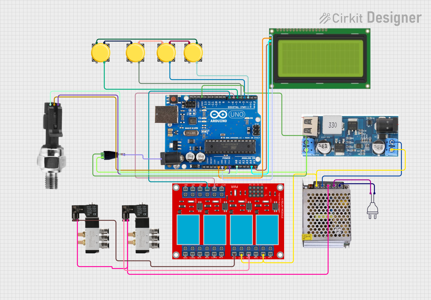
This circuit is designed to control a tyre inflator system using an Arduino Uno R3 microcontroller. The system includes multiple pushbuttons for user input, a solenoid valve for controlling air flow, an LCD display for user interface, and a pressure sensor for monitoring tyre pressure. The circuit also includes a power supply and a relay module for switching high-power components.
Component List
Pushbutton
- Description: A simple pushbutton used for user input.
- Pins: Pin 1, Pin 2, Pin 3, Pin 4
Arduino Uno R3
- Description: A microcontroller board based on the ATmega328P.
- Pins: D8, D9, D10, D11, D12, D13, GND, AREF, SDA, SCL, D0/RX, D1/Tx, D2, D3, D4, D5, 6, D7, A5/SCL, A4/SDA, A3, A2, A1, A0, Vin, 5V, 3.3V, RESET, IOREF, NONE, USB Jack, Power Jack
Solenoid Valve 5/2
- Description: A solenoid valve used to control the flow of air.
- Pins: 0V, 24V
LCD 20x4 I2C
- Description: A 20x4 character LCD display with I2C interface.
- Pins: GND, 5V, SCA, SCL
Power Supply 12V 5AMP
- Description: A power supply providing 12V DC at 5A.
- Pins: 220V Positive Pole (AC), 220V Negative Pole (AC), GND, GND (DC), 12V-24V Output (DC)
DCDC 12V/5V 3A
- Description: A DC-DC converter that steps down 12V to 5V.
- Pins: 12V (+), GND, 5V (+), Vin (+), V in (-)
Power 220V
- Description: A 220V AC power source.
- Pins: Hot wire, Neutral wire
4 Channel Relay Module
- Description: A relay module with 4 channels for switching high-power components.
- Pins: N.O. 4, COM 4, N.C. 4, N.O. 3, COM 3, N.C. 3, N.O. 2, COM 2, N.C. 2, N.O. 1, COM 1, N.C. 1, Pin 13, Pin 14, Pin 15, Pin 16, Pin 17, Pin 18, Pin 19, Pin 20, Pin 21, Pin 22, Pin 23, Pin 24, VCC+, VCC- (GND), IN 1, IN 2, IN 3, IN 4
Barrel Jack Male
- Description: A barrel jack connector for power input.
- Pins: Power Out, V+, V-
Industrial Pressure Sensor
- Description: A sensor used to measure pressure.
- Pins: DC+, DC-, Signal
Wiring Details
Pushbutton
Pushbutton 1
- Pin 1: Connected to Pin 3 of Pushbutton 2
- Pin 3: Connected to Pin 1 of Pushbutton 4
- Pin 4: Connected to D4 of Arduino Uno R3
Pushbutton 2
- Pin 1: Connected to Pin 3 of Pushbutton 3
- Pin 3: Connected to Pin 1 of Pushbutton 1
- Pin 4: Connected to D5 of Arduino Uno R3
Pushbutton 3
- Pin 1: Connected to Pin 3 of Pushbutton 2
- Pin 3: Connected to Pin 1 of Pushbutton 4
- Pin 4: Connected to D2 of Arduino Uno R3
Pushbutton 4
- Pin 1: Connected to Pin 3 of Pushbutton 3
- Pin 3: Connected to Pin 1 of Pushbutton 1
- Pin 4: Connected to D3 of Arduino Uno R3
Arduino Uno R3
- D2: Connected to Pin 4 of Pushbutton 3
- D3: Connected to Pin 4 of Pushbutton 4
- D4: Connected to Pin 4 of Pushbutton 1
- D5: Connected to Pin 4 of Pushbutton 2
- D7: Connected to IN 1 of 4 Channel Relay Module
- A0: Connected to Signal of Industrial Pressure Sensor
- A4/SDA: Connected to SCA of LCD 20x4 I2C
- A5/SCL: Connected to SCL of LCD 20x4 I2C
- Vin: Connected to DC+ of Industrial Pressure Sensor
- GND: Connected to GND of DCDC 12V/5V 3A, V- of Barrel Jack Male, DC- of Industrial Pressure Sensor, GND of LCD 20x4 I2C
- 5V: Connected to 5V of LCD 20x4 I2C
- Power Jack: Connected to Power Out of Barrel Jack Male
Solenoid Valve 5/2
Solenoid Valve 1
- 0V: Connected to GND of Power Supply 12V 5AMP
- 24V: Connected to N.O. 2 of 4 Channel Relay Module
Solenoid Valve 2
- 0V: Connected to GND of Power Supply 12V 5AMP
- 24V: Connected to N.C. 2 of 4 Channel Relay Module
LCD 20x4 I2C
- GND: Connected to GND of Arduino Uno R3
- 5V: Connected to 5V of Arduino Uno R3
- SCA: Connected to A4/SDA of Arduino Uno R3
- SCL: Connected to A5/SCL of Arduino Uno R3
Power Supply 12V 5AMP
- 220V Positive Pole (AC): Connected to Hot wire of Power 220V
- 220V Negative Pole (AC): Connected to Neutral wire of Power 220V
- GND (DC): Connected to V in (-) of DCDC 12V/5V 3A
- 12V-24V Output (DC): Connected to Vin (+) of DCDC 12V/5V 3A
DCDC 12V/5V 3A
- GND: Connected to GND of Arduino Uno R3, V- of Barrel Jack Male
- 5V (+): Connected to V+ of Barrel Jack Male
- Vin (+): Connected to 12V-24V Output (DC) of Power Supply 12V 5AMP
- V in (-): Connected to GND (DC) of Power Supply 12V 5AMP
4 Channel Relay Module
- VCC- (GND): Connected to 6 of Arduino Uno R3
- IN 1: Connected to D7 of Arduino Uno R3
- N.O. 2: Connected to 24V of Solenoid Valve 1
- N.C. 2: Connected to 24V of Solenoid Valve 2
- COM 1: Connected to COM 2 of 4 Channel Relay Module
- COM 2: Connected to COM 1 of 4 Channel Relay Module
Barrel Jack Male
- Power Out: Connected to Power Jack of Arduino Uno R3
- V+: Connected to 5V (+) of DCDC 12V/5V 3A
- V-: Connected to GND of DCDC 12V/5V 3A, GND of Arduino Uno R3
Industrial Pressure Sensor
- DC+: Connected to Vin of Arduino Uno R3
- DC-: Connected to GND of Arduino Uno R3
- Signal: Connected to A0 of Arduino Uno R3
Documented Code
#include <EEPROM.h>
#include <LiquidCrystal_I2C.h>
#include <Wire.h>

LiquidCrystal_I2C lcd(0x27, 20, 4);  // Device Address, N Character, LCD Lines
// SDA-> A4 SCL-> A5

int sensorPin = A0;
int setvalue = 0;

int sw_set = 2; // Connect to Switch Set
int sw_up = 3; // Connect to Switch UP
int sw_dwn = 4; // Connect to Switch Down
int sw_ent = 5; // Connect to Switch Enter

int purge = 6; // For Solenoid
int feed = 7; // For Solenoid

int max_pressure = 70;
int min_pressure = 10;
int pressure_value = 0;
int sensor_Value = 0;
int cal_factor = 0;
int set_mode = 0;
int threshold = 5;

int inf_delay = 200;
String disp