Cirkit Designer
Your all-in-one circuit design IDE
Home /
Project Documentation
Arduino UNO-Based Ultrasonic Sensor and DC Motor Control System with L298N Driver
Circuit Documentation
Summary
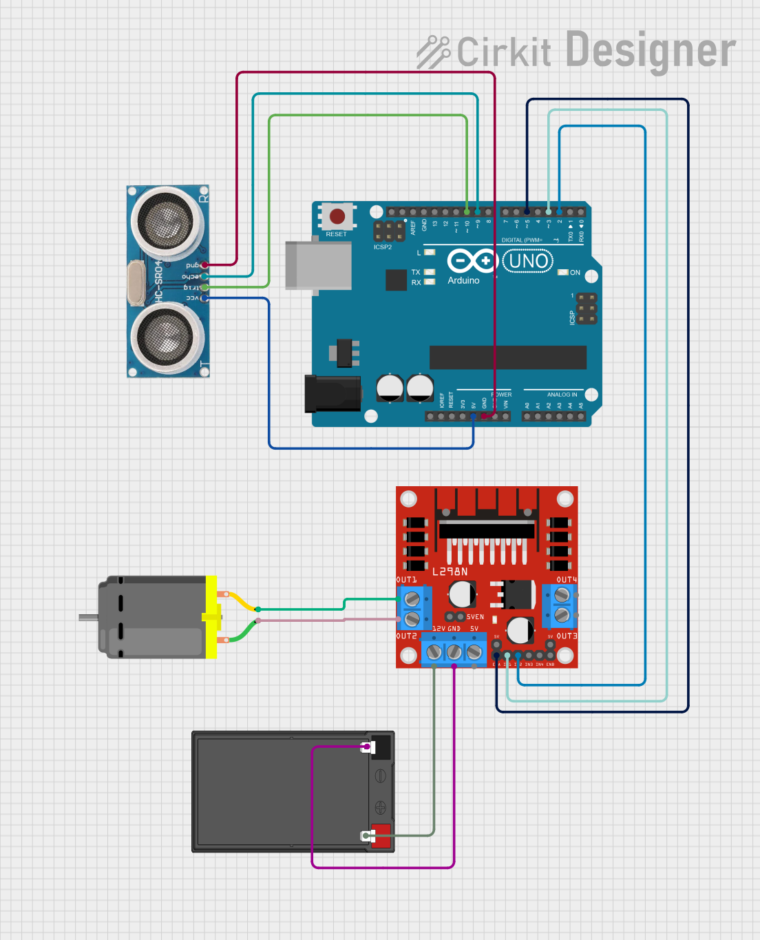
This document provides a detailed overview of a circuit that includes an Arduino UNO microcontroller, an Ultrasonic Sensor, an L298N DC motor driver, a 12V 7Ah Battery, and a DC Motor. The circuit is designed to control a DC motor based on input from the Ultrasonic Sensor, with the Arduino UNO serving as the central control unit.
Component List
Arduino UNO
- Description: A microcontroller board based on the ATmega328P.
- Pins: UNUSED, IOREF, Reset, 3.3V, 5V, GND, Vin, A0, A1, A2, A3, A4, A5, SCL, SDA, AREF, D13, D12, D11, D10, D9, D8, D7, D6, D5, D4, D3, D2, D1, D0
Ultrasonic Sensor
- Description: A sensor used to measure distance by using ultrasonic waves.
- Pins: +VCC, Trigger, Echo, GND
L298N DC Motor Driver
- Description: A dual H-bridge motor driver that allows control of the speed and direction of two DC motors.
- Pins: OUT1, OUT2, 12V, GND, 5V, OUT3, OUT4, 5V-ENA-JMP-I, 5V-ENA-JMP-O, +5V-J1, +5V-J2, ENA, IN1, IN2, IN3, IN4, ENB
12V 7Ah Battery
- Description: A rechargeable battery providing 12V power.
- Pins: 12v +, 12v -
DC Motor
- Description: A motor that runs on direct current (DC) electricity.
- Pins: pin 1, pin 2
Wiring Details
Arduino UNO
- 5V connected to +VCC of the Ultrasonic Sensor
- GND connected to GND of the Ultrasonic Sensor
- D10 connected to Trigger of the Ultrasonic Sensor
- D9 connected to Echo of the Ultrasonic Sensor
- D5 connected to ENA of the L298N DC Motor Driver
- D3 connected to IN1 of the L298N DC Motor Driver
- D2 connected to IN2 of the L298N DC Motor Driver
Ultrasonic Sensor
- +VCC connected to 5V of the Arduino UNO
- GND connected to GND of the Arduino UNO
- Trigger connected to D10 of the Arduino UNO
- Echo connected to D9 of the Arduino UNO
L298N DC Motor Driver
- ENA connected to D5 of the Arduino UNO
- IN1 connected to D3 of the Arduino UNO
- IN2 connected to D2 of the Arduino UNO
- OUT1 connected to pin 2 of the DC Motor
- OUT2 connected to pin 1 of the DC Motor
- 12V connected to 12v + of the 12V 7Ah Battery
- GND connected to 12v - of the 12V 7Ah Battery
12V 7Ah Battery
- 12v + connected to 12V of the L298N DC Motor Driver
- 12v - connected to GND of the L298N DC Motor Driver
DC Motor
- pin 2 connected to OUT1 of the L298N DC Motor Driver
- pin 1 connected to OUT2 of the L298N DC Motor Driver
Documented Code
Arduino UNO Code (sketch.ino)
void setup() {
  // put your setup code here, to run once:

}

void loop() {
  // put your main code here, to run repeatedly:

}
Additional Documentation (documentation.txt)
This document provides a comprehensive overview of the circuit, including a summary, component list, wiring details, and documented code.