Cirkit Designer
Your all-in-one circuit design IDE
Home /
Project Documentation
Arduino UNO Controlled LCD Display with Ultrasonic Sensors and Servomotor Interaction
Circuit Documentation
Summary
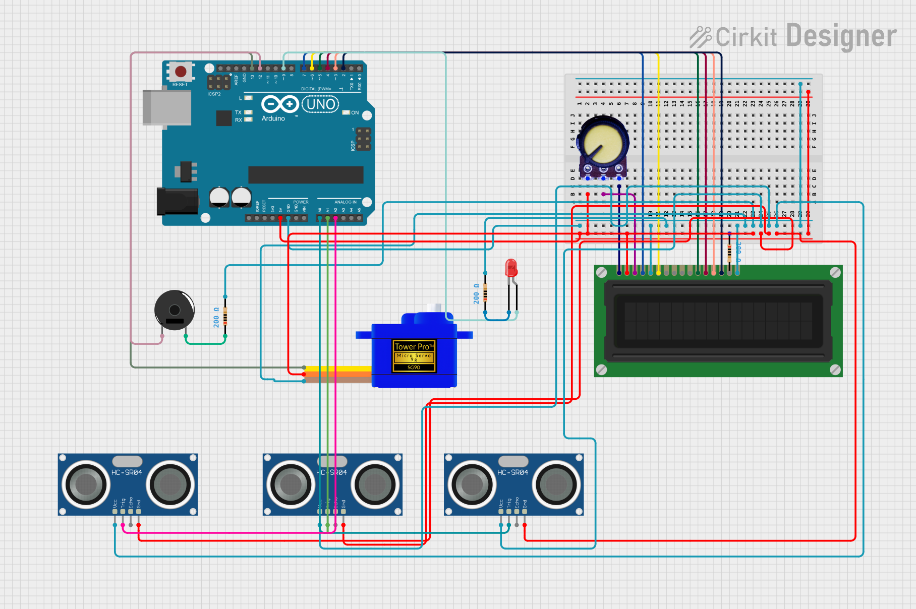
This circuit integrates various components with an Arduino UNO microcontroller to create a multifunctional system. The system includes an LCD display for user interface, a potentiometer for adjustable input, a servomotor for mechanical control, an LED for visual indication, resistors for current limiting, a piezo buzzer for audio output, and multiple HC-SR04 ultrasonic sensors for distance measurement.
Component List
Arduino UNO
- Microcontroller board based on the ATmega328P
- Provides digital and analog I/O pins for interfacing with other components
LCD Display (16 pin)
- A 16x2 character LCD display for showing information to the user
Potentiometer
- A variable resistor used to adjust the contrast of the LCD display
Servomotor SG90
- A small and lightweight servo for precise control of mechanical movement
LED: Two Pin (red)
- A red LED used as a visual indicator
Resistors (200 Ohms)
- Three resistors with a resistance of 200 Ohms, used for current limiting
Piezo Buzzer
- An electronic device that produces sound when voltage is applied
HC-SR04 Ultrasonic Sensors
- Three ultrasonic ranging modules used for measuring distances
Wiring Details
Arduino UNO
5VandGNDare used to power the circuitA0,A1,A2are connected to theTRIGpins of the HC-SR04 sensorsD13is connected to theSIGpin of the Servomotor SG90D12is connected to thepin 1of the Piezo BuzzerD9is connected to theanodeof the LEDD7,D6,D5,D4,D3,D2are connected to theRS,E,DB4,DB5,DB6,DB7pins of the LCD Display respectively
LCD Display (16 pin)
VDDconnected to5VpowerVSSandR_Wconnected toGNDVOconnected to theOutputof the PotentiometerRS,E,DB4,DB5,DB6,DB7connected to Arduino UNO pinsD7,D6,D5,D4,D3,D2respectivelyKconnected toGNDthrough a 200 Ohm resistor
Potentiometer
GNDconnected toGNDOutputconnected toVOof the LCD DisplayVCCconnected to5Vpower
Servomotor SG90
SIGconnected toD13on the Arduino UNOVCCconnected to5VpowerGNDconnected toGND
LED: Two Pin (red)
anodeconnected toD9on the Arduino UNOcathodeconnected toGNDthrough a 200 Ohm resistor
Resistors (200 Ohms)
- One resistor connected between the
cathodeof the LED andGND - One resistor connected between
Kof the LCD Display andGND - One resistor connected between
pin 2of the Piezo Buzzer andGND
Piezo Buzzer
pin 1connected toD12on the Arduino UNOpin 2connected toGNDthrough a 200 Ohm resistor
HC-SR04 Ultrasonic Sensors
VCCpins connected to5VpowerGNDpins connected toGNDTRIGpins connected toA0,A1,A2on the Arduino UNO respectively
Documented Code
sketch.ino
#include <LiquidCrystal.h>

// Initialize the library with the numbers of the interface pins
LiquidCrystal lcd(7, 6, 5, 4, 3, 2);

void setup() {
  // Set up the LCD's number of columns and rows:
  lcd.begin(16, 2);
  // Print a message to the LCD.
  lcd.print("hello");
}

void loop() {
  // put your main code here, to run repeatedly:

}
This code initializes the LCD display and prints the message "hello" on it. The LiquidCrystal library is used to manage the LCD's interface pins and to set up the display's dimensions. The setup() function runs once when the program starts and sets up the LCD, while the loop() function runs continuously, allowing for repeated operations.