
Arduino-Controlled Smoke Detection System with Buzzer and LED Alert
View and Edit Project In Cirkit Designer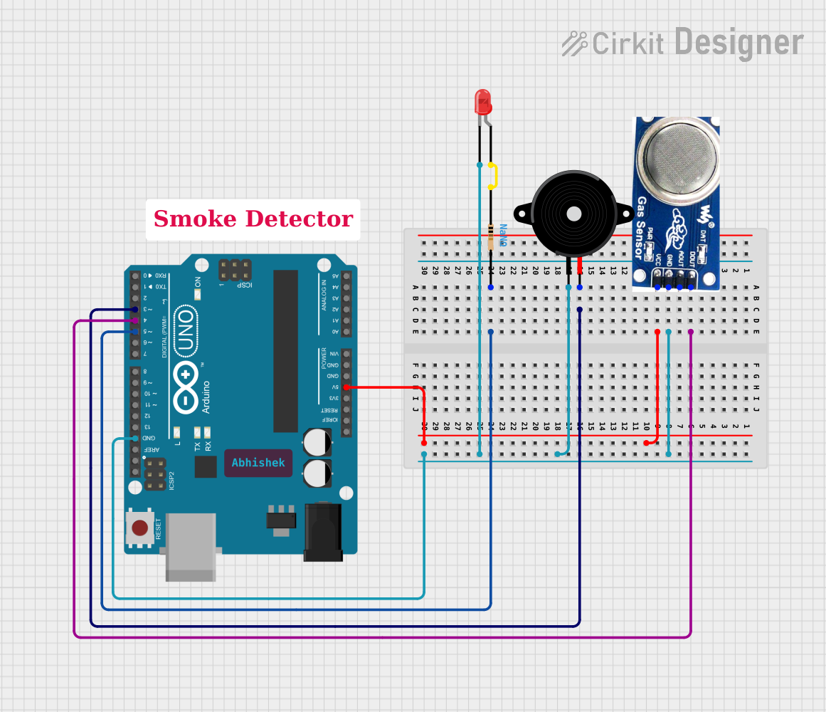
Circuit Documentation
Summary of the Circuit
This circuit is designed to detect smoke using a smoke sensor and to provide an alert through both visual and auditory indicators. When smoke is detected by the sensor, the circuit activates a piezo speaker to emit a sound and an LED to provide a visual signal. The core of the circuit is an Arduino UNO microcontroller, which reads the digital output from the smoke sensor and controls the activation of the piezo speaker and LED.
Component List
Smoke Sensor
- Pins: DO, AO, GND, VCC
- Description: A sensor that detects smoke and provides a digital output signal.
Piezo Speaker
- Pins: pin1, pin2
- Description: An electronic device that emits sound when an electrical signal is applied.
LED: Two Pin (red)
- Pins: cathode, anode
- Description: A red light-emitting diode that illuminates when current flows through it.
Resistor
- Pins: pin1, pin2
- Description: A passive two-terminal electrical component that implements electrical resistance as a circuit element.
Arduino UNO
- Pins: UNUSED, IOREF, Reset, 3.3V, 5V, GND, Vin, A0-A5, SCL, SDA, AREF, D0-D13
- Description: A microcontroller board based on the ATmega328P, with digital input/output pins, analog inputs, and various power options.
Comments
- Description: Non-electrical components used for annotations in the circuit design.
Wiring Details
Smoke Sensor
- DO (Digital Output): Connected to Arduino UNO D4
- GND (Ground): Connected to common ground net
- VCC (Power Supply): Connected to Arduino UNO 5V
Piezo Speaker
- pin1 (Ground): Connected to common ground net
- pin2 (Signal Input): Connected to Arduino UNO D3
LED: Two Pin (red)
- cathode (Negative): Connected to common ground net
- anode (Positive): Connected to one end of the resistor
Resistor
- pin1: Connected to LED anode
- pin2: Connected to Arduino UNO D5
Arduino UNO
- D4: Connected to Smoke Sensor DO
- D3: Connected to Piezo Speaker pin2
- D5: Connected to Resistor pin2
- GND: Connected to common ground net
- 5V: Connected to Smoke Sensor VCC
Documented Code
/*
 * Arduino Buzzer LED Smoke Sensor
 * This sketch reads the digital output from a smoke sensor and triggers a
 * piezo buzzer and an LED when smoke is detected.
 */

// Pin definitions
const int smokeSensorPin = 4; // Smoke sensor digital output connected to D4
const int buzzerPin = 3;      // Piezo buzzer connected to D3
const int ledPin = 5;         // LED connected to D5 through a resistor

void setup() {
  // Initialize the smoke sensor pin as an input
  pinMode(smokeSensorPin, INPUT);
  // Initialize the buzzer and LED pins as outputs
  pinMode(buzzerPin, OUTPUT);
  pinMode(ledPin, OUTPUT);
}

void loop() {
  // Read the smoke sensor value
  int smokeDetected = digitalRead(smokeSensorPin);
  if (smokeDetected == HIGH) {
    // Smoke detected, turn on buzzer and LED
    digitalWrite(buzzerPin, HIGH);
    digitalWrite(ledPin, HIGH);
  } else {
    // No smoke detected, turn off buzzer and LED
    digitalWrite(buzzerPin, LOW);
    digitalWrite(ledPin, LOW);
  }
  // Small delay to debounce sensor reading
  delay(100);
}
The code is written for the Arduino UNO microcontroller. It initializes the pins connected to the smoke sensor, piezo speaker, and LED. In the main loop, it continuously reads the digital output from the smoke sensor. If smoke is detected (indicated by a HIGH signal), it activates the piezo speaker and LED. If no smoke is detected, it deactivates both the speaker and LED. A short delay is included to debounce the sensor reading.