
ESP32-Powered Wi-Fi Controlled Robotic Car with Ultrasonic Obstacle Detection
View and Edit Project In Cirkit Designer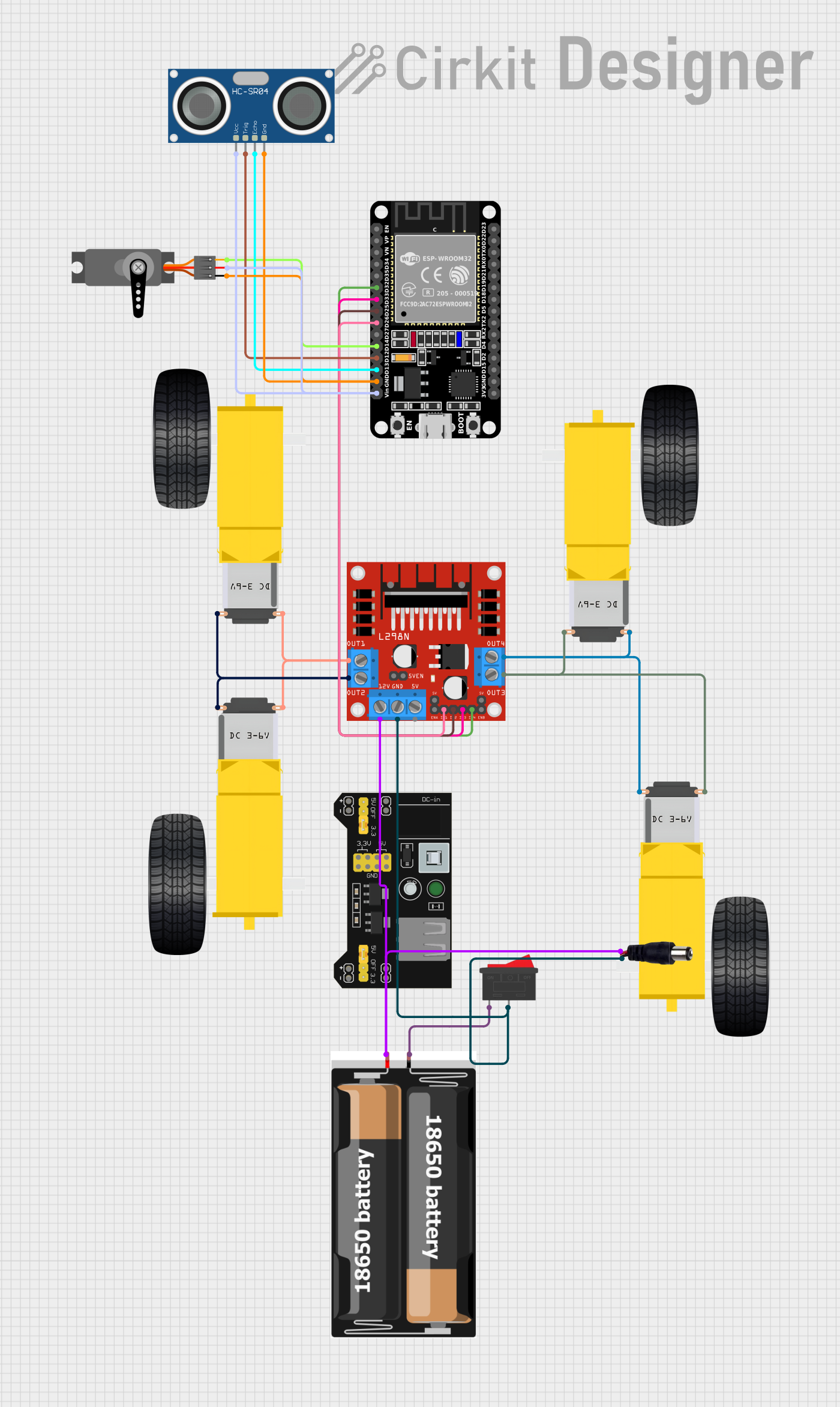
Circuit Documentation
Summary
This document provides a detailed overview of a circuit designed to control a robotic vehicle. The circuit includes an ESP32 microcontroller, motor drivers, DC motors, an ultrasonic sensor, a servo motor, a power supply, and a rocker switch. The ESP32 microcontroller is programmed to handle various tasks such as motor control, ultrasonic sensing, and communication.
Component List
L298N DC Motor Driver
- Description: Motor driver used to control the speed and direction of DC motors.
- Pins: OUT1, OUT2, 12V, GND, 5V, OUT3, OUT4, 5V-ENA-JMP-I, 5V-ENA-JMP-O, +5V-J1, +5V-J2, ENA, IN1, IN2, IN3, IN4, ENB
Gearmotor DC Wheels Left
- Description: DC motor used for the left wheels of the robotic vehicle.
- Pins: PIN1, PIN2
Gearmotor DC Wheels Right
- Description: DC motor used for the right wheels of the robotic vehicle.
- Pins: PIN1, PIN2
ESP32 (30 pin)
- Description: Microcontroller used for controlling the robotic vehicle.
- Pins: EN, VP, VN, D34, D35, D32, D33, D25, D26, D27, D14, D12, D13, GND, Vin, D23, D22, TX0, RX0, D21, D19, D18, D5, TX2, RX2, D4, D2, D15, 3V3
HC-SR04 Ultrasonic Sensor
- Description: Sensor used for distance measurement.
- Pins: VCC, TRIG, ECHO, GND
2x 18650
- Description: Battery pack used to power the circuit.
- Pins: vcc, gnd
MB102 Breadboard Power Supply Module 3.3V/5V
- Description: Power supply module used to provide 3.3V and 5V to the circuit.
- Pins: VCC, GND, 3.3V, 5V
Power Jack
- Description: Connector for external power supply.
- Pins: POSITIF, NEGATIF
Servo
- Description: Servo motor used for precise control of angular position.
- Pins: GND, VCC, PWM
Rocker Switch
- Description: Switch used to control the power supply to the circuit.
- Pins: 1, 2
Wiring Details
L298N DC Motor Driver
- IN1 connected to ESP32 D26
- IN2 connected to ESP32 D25
- IN3 connected to ESP32 D33
- IN4 connected to ESP32 D32
- OUT1 connected to Gearmotor DC Wheels Left PIN1 and Gearmotor DC Wheels Right PIN2
- OUT2 connected to Gearmotor DC Wheels Left PIN2 and Gearmotor DC Wheels Right PIN1
- OUT3 connected to Gearmotor DC Wheels Left PIN1 and Gearmotor DC Wheels Right PIN1
- OUT4 connected to Gearmotor DC Wheels Left PIN2 and Gearmotor DC Wheels Right PIN2
- 12V connected to 2x 18650 vcc and Power Jack POSITIF
- GND connected to Rocker Switch 2 and Power Jack NEGATIF
Gearmotor DC Wheels Left
- PIN1 connected to L298N DC Motor Driver OUT1 and L298N DC Motor Driver OUT3
- PIN2 connected to L298N DC Motor Driver OUT2 and L298N DC Motor Driver OUT4
Gearmotor DC Wheels Right
- PIN1 connected to L298N DC Motor Driver OUT2 and L298N DC Motor Driver OUT3
- PIN2 connected to L298N DC Motor Driver OUT1 and L298N DC Motor Driver OUT4
ESP32 (30 pin)
- D26 connected to L298N DC Motor Driver IN1
- D25 connected to L298N DC Motor Driver IN2
- D33 connected to L298N DC Motor Driver IN3
- D32 connected to L298N DC Motor Driver IN4
- D14 connected to Servo PWM
- D12 connected to HC-SR04 Ultrasonic Sensor TRIG
- D13 connected to HC-SR04 Ultrasonic Sensor ECHO
- GND connected to HC-SR04 Ultrasonic Sensor GND and Servo GND
- Vin connected to HC-SR04 Ultrasonic Sensor VCC and Servo VCC
HC-SR04 Ultrasonic Sensor
- TRIG connected to ESP32 D12
- ECHO connected to ESP32 D13
- GND connected to ESP32 GND
- VCC connected to ESP32 Vin
2x 18650
- vcc connected to L298N DC Motor Driver 12V and Power Jack POSITIF
- gnd connected to Rocker Switch 1
MB102 Breadboard Power Supply Module 3.3V/5V
- VCC not connected
- GND not connected
- 3.3V not connected
- 5V not connected
Power Jack
- POSITIF connected to 2x 18650 vcc and L298N DC Motor Driver 12V
- NEGATIF connected to L298N DC Motor Driver GND and Rocker Switch 2
Servo
- GND connected to ESP32 GND
- VCC connected to ESP32 Vin
- PWM connected to ESP32 D14
Rocker Switch
- 1 connected to 2x 18650 gnd
- 2 connected to L298N DC Motor Driver GND and Power Jack NEGATIF
Code Documentation
ESP32 Code (sketch.ino)
void setup() {
  // put your setup code here, to run once:

}

void loop() {
  // put your main code here, to run repeatedly:

}
ESP32 Code Documentation (documentation.txt)
# VAIO Code logic

## Setup
- Motor Wheels Setup task
- Ultrasonic Setup task (For automatic)
- Bluetooth Setup task (for DS4)
- ESP Now Setup (For hand gesture & Voice Recognition)

## Operational
- Master Controller Task (Handles the state of communication) (Priority 2)
- Voice Recognition Task (Probably uses Interrupt i.e has the highest priority) (Priority 1)
- Automatic Task (uses ultrasonic) (Priority 3)
- DS4 Task (uses bluetooth) (Priority 3)
- Hand Gesture Task (uses ESP-NOW) (Priority 3)

### Voice Recognition Task (Called when interrupted by the voice module from the hand gesture ESP32)
- ESP-NOW communication has to be always active for voice communication

### Master Controller Task (Called everytime by Voice Recognition Task)
- This task will be execute by Voice Recognition Task
- Implement enums for the state
- Calls either the Automatic Task, DS4 Task, or Hand Gesture Task depending on the state

### Automatic Task (Task is looping)
- This task will be execute by Master Controller Task

### DS4 Task (Task is looping)
- This task will be execute by Master Controller Task

### Hand Gesture Task (Task is looping)
- This task will be execute by Master Controller Task

## Some logic ideas
ESP32 has 2 cores. Core 1 execute Master Controller Task. Core 2 execute Voice Recognition Task

Voice Recognition Task in Core 2 will always be ready to listen for ESP-NOW communication for the voice command. If communication has been heard,
it will process the command and interrupt task in Core 1 by calling the Master Controller Task to change the state of the controls.

Note : Keep in mind of accidentally resetting the watchdog timer