Cirkit Designer
Your all-in-one circuit design IDE
Home /
Project Documentation
Arduino UNO Based Smart Irrigation System with Soil Moisture and Rain Sensing
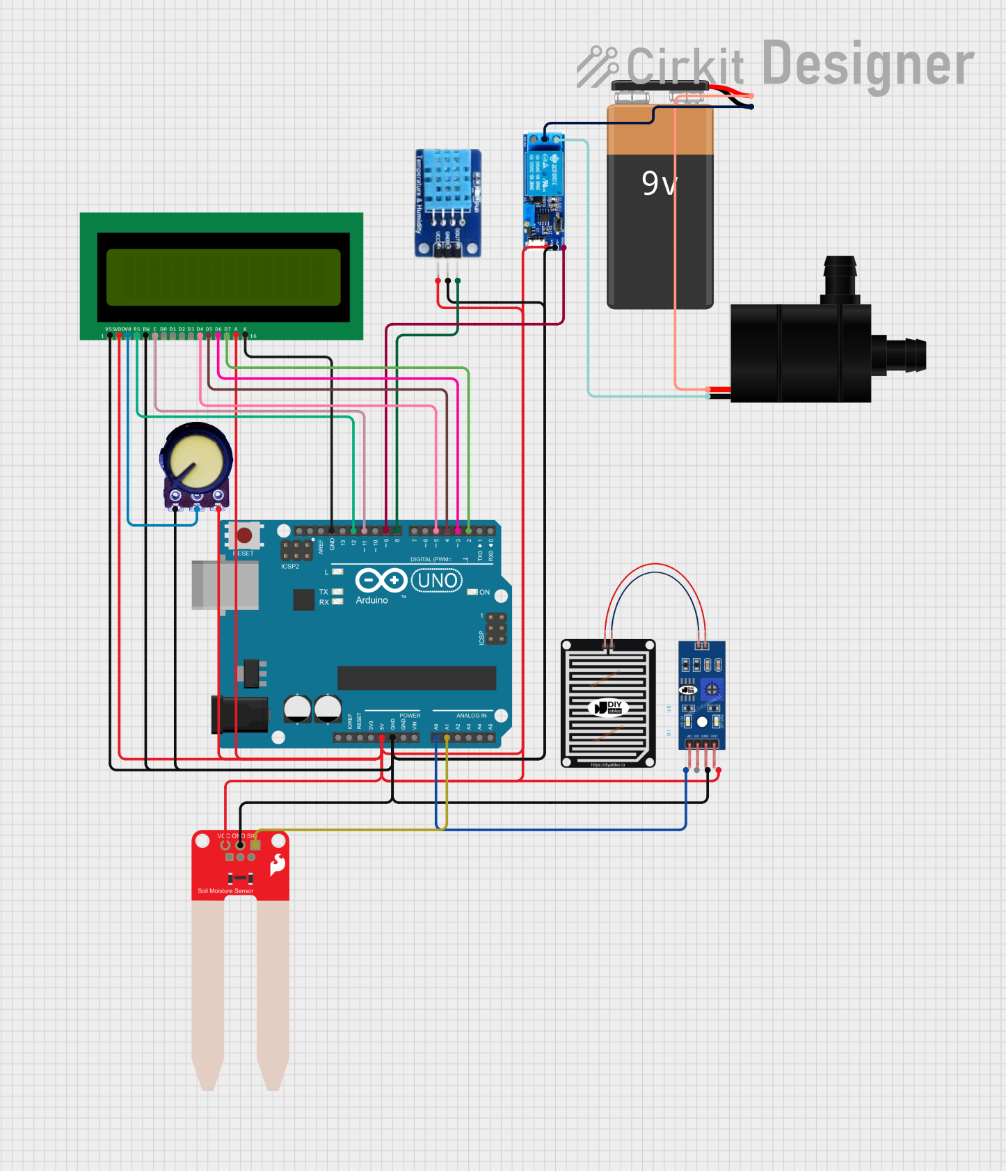
Smart Irrigation System Circuit Documentation
Summary
The Smart Irrigation System is designed to automate the watering process based on soil moisture levels and rain detection. It utilizes an Arduino UNO as the central processing unit, interfacing with a rain sensor, a soil moisture sensor, a DHT11 temperature and humidity sensor, a 16x2 LCD for display, a potentiometer for LCD contrast adjustment, a relay module to control a water pump, and a 9V battery as the power source.
Component List
Arduino UNO
- Microcontroller board based on the ATmega328P
- Used for controlling the sensors, LCD, and relay module
RAIN SENSOR
- Detects rainwater
- Provides digital and analog outputs
16X2 LCD
- Alphanumeric Liquid Crystal Display
- Displays humidity, temperature, and soil moisture levels
Potentiometer
- Variable resistor
- Adjusts the contrast of the LCD
DHT11
- Temperature and humidity sensor
- Measures ambient temperature and humidity
Water Pump
- Electric pump
- Pumps water for irrigation when activated
Relay module 5v-30v
- Electrically operated switch
- Controls the power to the water pump
9V Battery
- Provides power to the water pump
SparkFun Soil Moisture Sensor
- Measures the moisture level in the soil
- Provides digital and analog outputs
Wiring Details
Arduino UNO
- 5V and GND pins provide power to the sensors, LCD, and relay module
- A0 pin connected to the moisture sensor
- A1 pin connected to the rain sensor
- D12 pin connected to the RS pin of the LCD
- D11 pin connected to the E pin of the LCD
- D5, D4, D3, D2 pins connected to the D4, D5, D6, D7 pins of the LCD respectively
- D9 pin connected to the trigger pin of the relay module
- D8 pin connected to the DATA pin of the DHT11 sensor
RAIN SENSOR
- VCC and GRD pins connected to 5V and GND for power
- AO pin connected to A0 on the Arduino UNO for analog signal
16X2 LCD
- VDD and A pins connected to 5V for power
- VSS and K pins connected to GND
- V0 pin connected to the output of the potentiometer for contrast adjustment
- RS, E, D4, D5, D6, D7 pins connected to D12, D11, D5, D4, D3, D2 on the Arduino UNO
Potentiometer
- VCC and GND pins connected to 5V and GND for power
- Output pin connected to V0 on the LCD for contrast control
DHT11
- VCC and GND pins connected to 5V and GND for power
- DATA pin connected to D8 on the Arduino UNO
Water Pump
- VCC pin connected to the normally open contact of the relay module
- GND pin connected to the 9V battery negative terminal
Relay module 5v-30v
- V+ and V- pins connected to 5V and GND for power
- Trigger pin connected to D9 on the Arduino UNO
- Common contact connected to the 9V battery positive terminal
- Normally open contact connected to the VCC pin of the water pump
9V Battery
- Positive terminal connected to the common contact of the relay module
- Negative terminal connected to the GND pin of the water pump
SparkFun Soil Moisture Sensor
- VCC and GND pins connected to 5V and GND for power
- SIG pin connected to A0 on the Arduino UNO for analog signal
Documented Code
// Include the library code:
#include <LiquidCrystal.h>
#include "DHT.h"

// Initialize the LCD and set the pins
const int rs = 12, en = 11, d4 = 5, d5 = 4, d6 = 3, d7 = 2;
LiquidCrystal lcd(rs, en, d4, d5, d6, d7);

// Define sensor and relay pins
const int relay_Pin = 9;
const int DHT11_Sensor = 8;
const int moisture_sensor = A0;
const int rain_Sensor = A1;

// Define DHT sensor type
#define DHTTYPE DHT11
DHT dht(DHT11_Sensor, DHTTYPE);

// Variables to store sensor values
int moisture_sensor_value;
int rain_Sensor_value;
float humidity_value, temperature_value;

void setup() {
  Serial.begin(9600);
  pinMode(relay_Pin, OUTPUT);
  lcd.begin(16, 2);
  lcd.print("Smart Irrigation");
  lcd.setCursor(0, 1);
  lcd.print("SYSTEM");
  digitalWrite(relay_Pin, LOW);
  dht.begin();
  delay(2000);
}

void loop() {
  readDHT11_Sensor();
  moisture_level_detected();
  water_motor_start();
}

void readDHT11_Sensor() {
  humidity_value = dht.readHumidity();
  temperature_value = dht.readTemperature();

  if (isnan(humidity_value) || isnan(temperature_value)) {
    Serial.println("Failed to read from DHT sensor!");
    return;
  }

  Serial.print("Humidity: ");
  Serial.print(humidity_value);
  Serial.println("%");
  lcd.clear();
  lcd.print("Humidity %: ");
  lcd.setCursor(0, 1);
  lcd.print(humidity_value);
  delay(1000);

  Serial.print("Temperature: ");
  Serial.print(temperature_value);
  Serial.println("C");
  lcd.clear();
  lcd.print("Temperature C ");
  lcd.setCursor(0, 1);
  lcd.print(temperature_value);
  delay(1000);
}

void moisture_level_detected() {
  moisture_sensor_value = analogRead(moisture_sensor);
  Serial.print("Moisture Level: ");
  Serial.println(moisture_sensor_value);
  lcd.clear();
  lcd.print("Moisture Level:");
  lcd.setCursor(0, 1);
  lcd.print(moisture_sensor_value);
  delay(2000);
}

void water_motor_start() {
  rain_Sensor_value = analogRead(rain_Sensor);
  Serial.print("Rain sensor value: ");
  Serial.println(rain_Sensor_value);
  delay(1000);

  if (rain_Sensor_value > 700) {
    if (moisture_sensor_value > 700) {
      digitalWrite(relay_Pin, HIGH);
      delay(2000);
    } else {
      digitalWrite(relay_Pin, LOW);
      delay(2000);
    }
  } else {
    digitalWrite(relay_Pin, LOW);
    delay(2000);
  }
}
This code controls the Smart Irrigation System by reading sensor data, displaying it on the LCD, and controlling the water pump via the relay module based on the moisture and rain sensor readings.