
ESP8266-Based Obstacle Detection and Alert System with IR Sensor, Buzzer, and Relay-Controlled Motor
View and Edit Project In Cirkit Designer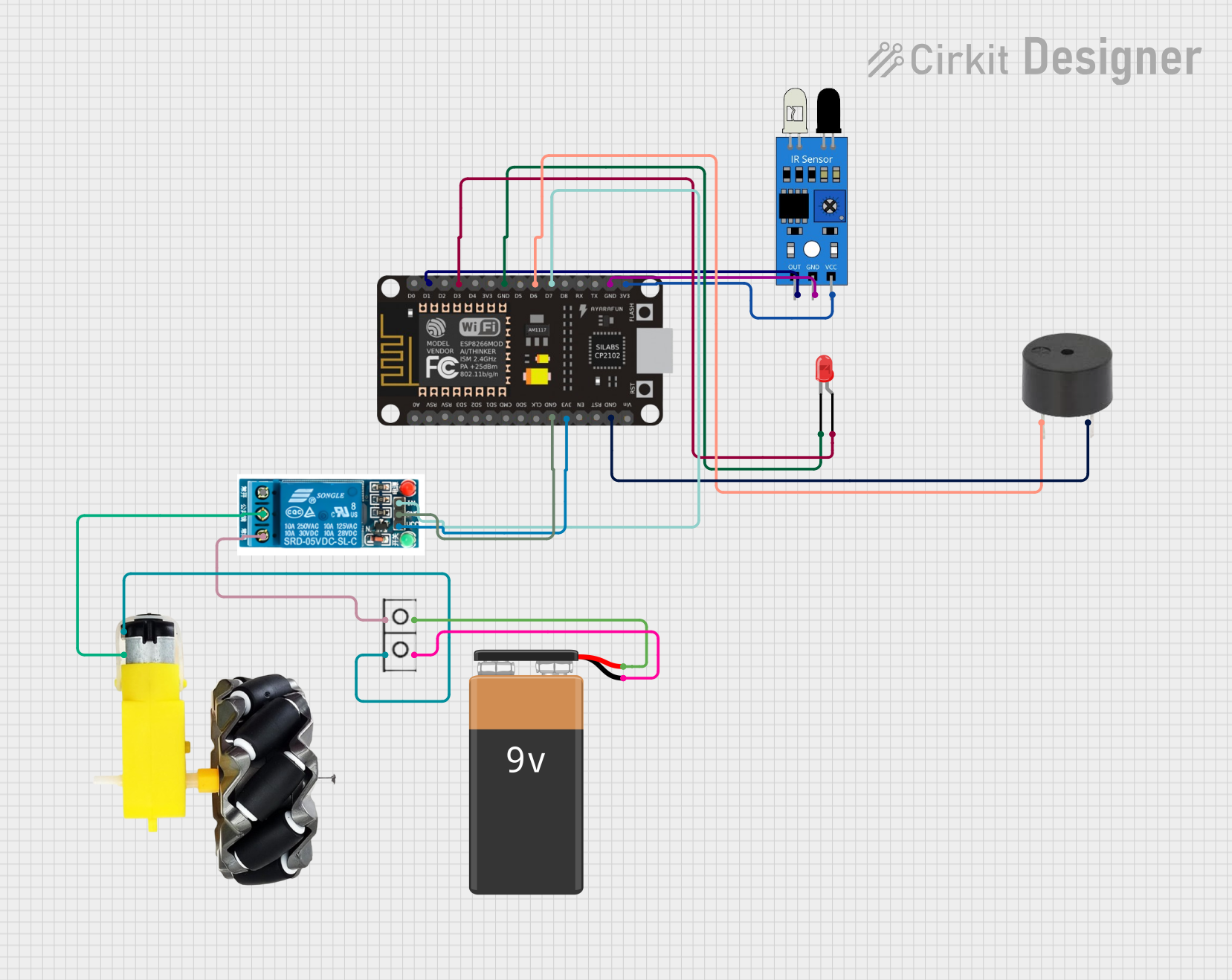
Circuit Documentation
Summary
This circuit is designed to detect obstacles using an IR sensor and respond by cutting off power to a motor, activating a buzzer, and lighting up an LED. The control logic is implemented using an ESP8266 NodeMCU microcontroller. The circuit also includes a 5V relay to control the motor and a 9V battery as the power source.
Component List
ESP8266 NodeMCU
- Description: A low-cost Wi-Fi microcontroller with multiple GPIO pins.
- Pins: D0, D1, D2, D3, D4, 3V3, GND, D5, D6, D7, D8, RX, TX, A0, RSV, SD3, SD2, SD1, CMD, SD0, CLK, EN, RST, VIN
IR Sensor
- Description: An infrared sensor used to detect obstacles.
- Pins: out, gnd, vcc
LED: Two Pin (red)
- Description: A red LED used to indicate the presence of an obstacle.
- Pins: cathode, anode
Buzzer
- Description: An audio signaling device used to alert the user.
- Pins: PIN, GND
5V Relay
- Description: A relay used to control the power supply to the motor.
- Pins: Normally Open, Common terminal, Normally Closed, In, GND, VCC
9V Battery
- Description: A 9V battery used as the power source for the circuit.
- Pins: -, +
Motor and Wheels
- Description: A motor with attached wheels, controlled by the relay.
- Pins: vcc, GND
Wire Connector
- Description: A connector used to manage wiring connections.
- Pins: +, -
Wiring Details
ESP8266 NodeMCU
- D1: Connected to IR sensor (out)
- D3: Connected to LED (anode)
- GND: Connected to LED (cathode)
- D6: Connected to buzzer (PIN)
- D7: Connected to 5V relay (In)
- GND: Connected to IR sensor (gnd)
- 3V3: Connected to IR sensor (vcc)
- GND: Connected to 5V relay (GND)
- 3V3: Connected to 5V relay (VCC)
- GND: Connected to buzzer (GND)
IR Sensor
- out: Connected to ESP8266 NodeMCU (D1)
- gnd: Connected to ESP8266 NodeMCU (GND)
- vcc: Connected to ESP8266 NodeMCU (3V3)
LED: Two Pin (red)
- anode: Connected to ESP8266 NodeMCU (D3)
- cathode: Connected to ESP8266 NodeMCU (GND)
Buzzer
- PIN: Connected to ESP8266 NodeMCU (D6)
- GND: Connected to ESP8266 NodeMCU (GND)
5V Relay
- In: Connected to ESP8266 NodeMCU (D7)
- GND: Connected to ESP8266 NodeMCU (GND)
- VCC: Connected to ESP8266 NodeMCU (3V3)
- Common terminal: Connected to motor and wheels (GND)
- Normally Closed: Connected to wire connector (+)
9V Battery
- -: Connected to wire connector (-)
- +: Connected to wire connector (+)
Motor and Wheels
- vcc: Connected to wire connector (-)
- GND: Connected to 5V relay (Common terminal)
Wire Connector
- +: Connected to 5V relay (Normally Closed)
- -: Connected to 9V battery (-)
- +: Connected to 9V battery (+)
- -: Connected to motor and wheels (vcc)
Code Documentation
// Include necessary libraries

// Define pin numbers for components
#define IR_PIN D1        // IR sensor input pin
#define RELAY_PIN D7     // Relay control pin
#define BUZZER_PIN D3    // Buzzer output pin
#define LED_PIN D6       // LED output pin

void setup() {
  // Start serial communication for debugging
  Serial.begin(115200);

  // Set pin modes for input and output
  pinMode(IR_PIN, INPUT);        // IR sensor pin as input
  pinMode(RELAY_PIN, OUTPUT);    // Relay control pin as output
  pinMode(BUZZER_PIN, OUTPUT);   // Buzzer pin as output
  pinMode(LED_PIN, OUTPUT);      // LED pin as output

  // Set initial states for the components
  digitalWrite(RELAY_PIN, HIGH);  // Initially, power is supplied to the motor (relay off)
  digitalWrite(BUZZER_PIN, LOW);  // Buzzer off
  digitalWrite(LED_PIN, LOW);     // LED off
}

void loop() {
  // Read the IR sensor value to detect obstacles
  int irValue = digitalRead(IR_PIN);

  // If an obstacle is detected (IR sensor value LOW), cut off the power supply
  if (irValue == LOW) {
    digitalWrite(RELAY_PIN, LOW);  // Relay cuts off power supply
    digitalWrite(BUZZER_PIN, HIGH); // Turn on buzzer to alert the user
    digitalWrite(LED_PIN, HIGH);    // Turn on LED to indicate braking mode
    Serial.println("Obstacle detected, power supply cut off...");

  } else {
    digitalWrite(RELAY_PIN, HIGH);   // Relay supplies power to the motor (no obstacle)
    digitalWrite(BUZZER_PIN, LOW);   // Turn off buzzer
    digitalWrite(LED_PIN, LOW);      // Turn off LED
    Serial.println("No obstacle detected, normal operation...");
  }

  delay(100); // Short delay for stable operation
}
This code initializes the pins for the IR sensor, relay, buzzer, and LED. It continuously reads the IR sensor value to detect obstacles. If an obstacle is detected, it cuts off the power supply to the motor, turns on the buzzer, and lights up the LED. If no obstacle is detected, it supplies power to the motor, turns off the buzzer, and turns off the LED.