
Arduino UNO Line Follower Robot with IR Sensors and L298N Motor Driver
View and Edit Project In Cirkit Designer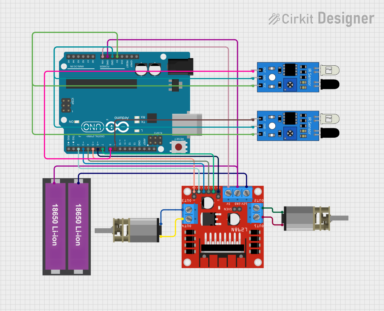
Circuit Documentation
Summary
This document provides a detailed overview of a line follower robot circuit. The circuit uses two IR sensors to detect the line and two DC motors to adjust the robot's direction. The control logic is implemented using an Arduino UNO microcontroller, which interfaces with an L298N DC motor driver to control the motors. The circuit is powered by two 18650 Li-ion batteries.
Component List
IR Sensor
- Description: Infrared sensor used to detect the line.
- Pins:
out,gnd,vcc
L298N DC Motor Driver
- Description: Motor driver used to control the DC motors.
- Pins:
OUT1,OUT2,12V,GND,5V,OUT3,OUT4,5V-ENA-JMP-I,5V-ENA-JMP-O,+5V-J1,+5V-J2,ENA,IN1,IN2,IN3,IN4,ENB
DC Mini Metal Gear Motor
- Description: DC motor used for driving the robot.
- Pins:
IN1,IN2
18650 Li-ion Battery x 2
- Description: Power source for the circuit.
- Pins:
+,-
Arduino UNO
- Description: Microcontroller used to control the robot.
- Pins:
UNUSED,IOREF,Reset,3.3V,5V,GND,Vin,A0,A1,A2,A3,A4,A5,SCL,SDA,AREF,D13,D12,D11,D10,D9,D8,D7,D6,D5,D4,D3,D2,D1,D0
Wiring Details
IR Sensor 1
- Pin
vccconnected to Arduino UNO5V - Pin
gndconnected to Arduino UNOGND - Pin
outconnected to Arduino UNOD8
IR Sensor 2
- Pin
vccconnected to Arduino UNO5V - Pin
gndconnected to Arduino UNOGND - Pin
outconnected to Arduino UNOD9
L298N DC Motor Driver
- Pin
GNDconnected to 18650 Li-ion Battery-and Arduino UNOGND - Pin
5Vconnected to Arduino UNOVin - Pin
12Vconnected to 18650 Li-ion Battery+ - Pin
IN1connected to Arduino UNOD7 - Pin
IN2connected to Arduino UNOD4 - Pin
IN3connected to Arduino UNOD3 - Pin
IN4connected to Arduino UNOD2 - Pin
ENAconnected to Arduino UNOD6 - Pin
ENBconnected to Arduino UNOD5 - Pin
OUT1connected to DC Mini Metal Gear Motor 1IN2 - Pin
OUT2connected to DC Mini Metal Gear Motor 1IN1 - Pin
OUT3connected to DC Mini Metal Gear Motor 2IN2 - Pin
OUT4connected to DC Mini Metal Gear Motor 2IN1
DC Mini Metal Gear Motor 1
- Pin
IN1connected to L298N DC Motor DriverOUT2 - Pin
IN2connected to L298N DC Motor DriverOUT1
DC Mini Metal Gear Motor 2
- Pin
IN1connected to L298N DC Motor DriverOUT4 - Pin
IN2connected to L298N DC Motor DriverOUT3
18650 Li-ion Battery x 2
- Pin
+connected to L298N DC Motor Driver12V - Pin
-connected to L298N DC Motor DriverGNDand Arduino UNOGND
Code Documentation
/*
 * Arduino Line Follower Robot
 * This code controls a line follower robot using two IR sensors and two DC motors.
 * The IR sensors detect the line and the motors adjust the robot's direction.
 */

// Pin definitions
const int irSensorLeft = 8;
const int irSensorRight = 9;
const int motorLeftForward = 7;
const int motorLeftBackward = 4;
const int motorRightForward = 3;
const int motorRightBackward = 2;
const int enableLeft = 6;
const int enableRight = 5;

void setup() {
  // Initialize IR sensor pins as inputs
  pinMode(irSensorLeft, INPUT);
  pinMode(irSensorRight, INPUT);

  // Initialize motor control pins as outputs
  pinMode(motorLeftForward, OUTPUT);
  pinMode(motorLeftBackward, OUTPUT);
  pinMode(motorRightForward, OUTPUT);
  pinMode(motorRightBackward, OUTPUT);
  pinMode(enableLeft, OUTPUT);
  pinMode(enableRight, OUTPUT);

  // Enable motors
  digitalWrite(enableLeft, HIGH);
  digitalWrite(enableRight, HIGH);
}

void loop() {
  // Read IR sensor values
  int leftSensorValue = digitalRead(irSensorLeft);
  int rightSensorValue = digitalRead(irSensorRight);

  // Determine motor actions based on sensor values
  if (leftSensorValue == LOW && rightSensorValue == LOW) {
    // Both sensors on the line, move forward
    moveForward();
  } else if (leftSensorValue == LOW && rightSensorValue == HIGH) {
    // Left sensor on the line, right sensor off the line, turn right
    turnRight();
  } else if (leftSensorValue == HIGH && rightSensorValue == LOW) {
    // Right sensor on the line, left sensor off the line, turn left
    turnLeft();
  } else {
    // Both sensors off the line, stop
    stopMoving();
  }
}

void moveForward() {
  digitalWrite(motorLeftForward, HIGH);
  digitalWrite(motorLeftBackward, LOW);
  digitalWrite(motorRightForward, HIGH);
  digitalWrite(motorRightBackward, LOW);
}

void turnRight() {
  digitalWrite(motorLeftForward, HIGH);
  digitalWrite(motorLeftBackward, LOW);
  digitalWrite(motorRightForward, LOW);
  digitalWrite(motorRightBackward, HIGH);
}

void turnLeft() {
  digitalWrite(motorLeftForward, LOW);
  digitalWrite(motorLeftBackward, HIGH);
  digitalWrite(motorRightForward, HIGH);
  digitalWrite(motorRightBackward, LOW);
}

void stopMoving() {
  digitalWrite(motorLeftForward, LOW);
  digitalWrite(motorLeftBackward, LOW);
  digitalWrite(motorRightForward, LOW);
  digitalWrite(motorRightBackward, LOW);
}
This code controls the line follower robot by reading the values from the IR sensors and adjusting the motor directions accordingly. The setup function initializes the pins, and the loop function continuously checks the sensor values to determine the robot's movement. The helper functions moveForward, turnRight, turnLeft, and stopMoving control the motor actions.