
ESP32-Based Smart Door Lock with RFID, Keypad, and LCD Display
View and Edit Project In Cirkit Designer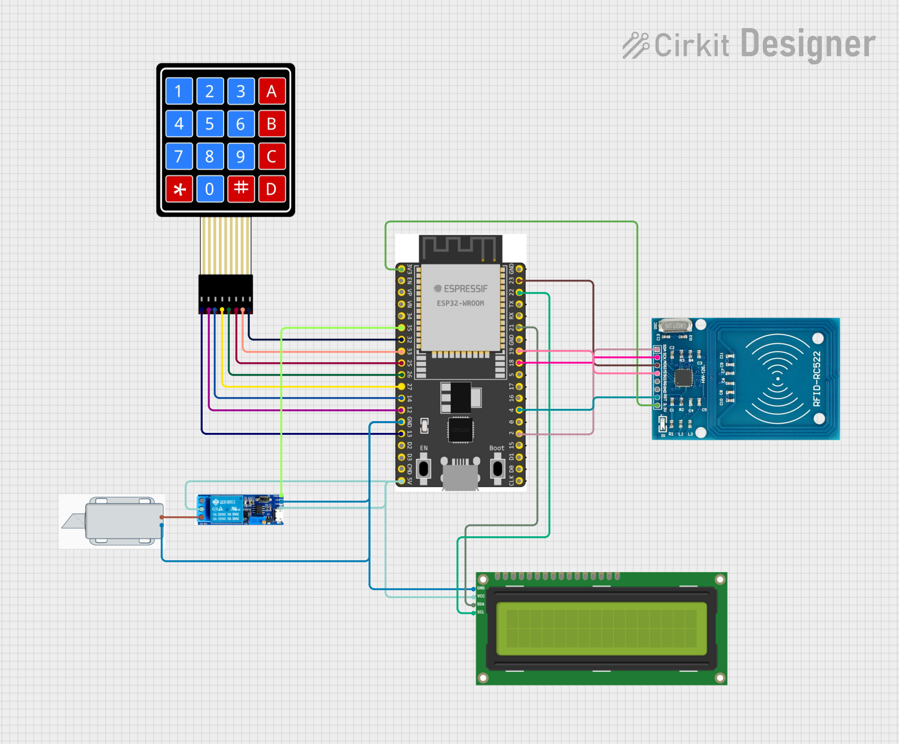
Smart Door Lock Circuit Documentation
Summary
This document provides a detailed overview of a smart door lock system. The system integrates an RFID reader, a 4x4 membrane keypad, an ESP32 microcontroller, an I2C LCD screen, a relay module, and a 12V solenoid lock. The ESP32 microcontroller serves as the central control unit, interfacing with the other components to manage access control via RFID cards and keypad input.
Component List
RFID-RC522
- Description: RFID reader module
- Pins: VCC (3.3V), RST, GND, IRQ, MISO, MOSI, SCK, SDA
- Purpose: Reads RFID cards to authenticate users.
4X4 Membrane Matrix Keypad
- Description: 4x4 matrix keypad
- Pins: R1, R2, R3, R4, C1, C2, C3, C4
- Purpose: Allows users to input a passcode for authentication.
ESP32 Wroom Dev Kit
- Description: ESP32 development board
- Pins: 3V3, EN, VP, VN, GPIO 34, GPIO 35, GPIO 32, GPIO 33, GPIO 25, GPIO 26, GPIO 27, GPIO 14, GND, GPIO 13, SD2, SD3, CMD, V5, GPIO 23, GPIO 22, TXD, RXD, GPIO 21, GPIO 19, GPIO 18, GPIO 5, GPIO 17, GPIO 16, GPIO 4, GPIO 0, GPIO 2, GPIO 15, SD1, SD0, CLK
- Purpose: Central control unit for the smart door lock system.
I2C LCD 16x2 Screen
- Description: 16x2 character LCD with I2C interface
- Pins: SCL, SDA, VCC (5V), GND, VDD, VO, RS, RW, E, D0, D1, D2, D3, D4, D5, D6, D7, BLA, BLK
- Purpose: Displays messages to the user.
Relay Module 5V-30V
- Description: Relay module
- Pins: Common contact, Normally open, Normally closed, Trigger, V-, V+
- Purpose: Controls the power to the solenoid lock.
12V Solenoid Lock
- Description: Electromechanical lock
- Pins: -, +
- Purpose: Locks and unlocks the door.
Wiring Details
RFID-RC522
- VCC (3.3V): Connected to ESP32 pin 3V3
- RST: Connected to ESP32 pin GPIO 4
- GND: Connected to common ground
- MISO: Connected to ESP32 pin GPIO 19
- MOSI: Connected to ESP32 pin GPIO 23
- SCK: Connected to ESP32 pin GPIO 18
- SDA: Connected to ESP32 pin GPIO 2
4X4 Membrane Matrix Keypad
- R1: Connected to ESP32 pin GPIO 13
- R2: Connected to ESP32 pin GPIO 14
- R3: Connected to ESP32 pin GPIO 14
- R4: Connected to ESP32 pin GPIO 27
- C1: Connected to ESP32 pin GPIO 26
- C2: Connected to ESP32 pin GPIO 25
- C3: Connected to ESP32 pin GPIO 33
- C4: Connected to ESP32 pin GPIO 32
ESP32 Wroom Dev Kit
- 3V3: Connected to RFID-RC522 pin VCC (3.3V)
- GND: Connected to common ground
- GPIO 2: Connected to RFID-RC522 pin SDA
- GPIO 4: Connected to RFID-RC522 pin RST
- GPIO 13: Connected to Keypad pin R1
- GPIO 14: Connected to Keypad pins R2, R3
- GPIO 18: Connected to RFID-RC522 pin SCK
- GPIO 19: Connected to RFID-RC522 pin MISO
- GPIO 21: Connected to LCD pin SDA
- GPIO 22: Connected to LCD pin SCL
- GPIO 23: Connected to RFID-RC522 pin MOSI
- GPIO 25: Connected to Keypad pin C2
- GPIO 26: Connected to Keypad pin C1
- GPIO 27: Connected to Keypad pin R4
- GPIO 32: Connected to Keypad pin C4
- GPIO 33: Connected to Keypad pin C3
- GPIO 35: Connected to Relay pin Trigger
- V5: Connected to LCD pin VCC (5V) and Relay pins Common contact, V+
I2C LCD 16x2 Screen
- SCL: Connected to ESP32 pin GPIO 22
- SDA: Connected to ESP32 pin GPIO 21
- VCC (5V): Connected to ESP32 pin V5
- GND: Connected to common ground
Relay Module 5V-30V
- Trigger: Connected to ESP32 pin GPIO 35
- V-: Connected to common ground
- V+: Connected to ESP32 pin V5
- Common contact: Connected to ESP32 pin V5
- Normally closed: Connected to Solenoid Lock pin +
12V Solenoid Lock
- +: Connected to Relay pin Normally closed
- -: Connected to common ground
Code Documentation
#include <Wire.h>
#include <LiquidCrystal_I2C.h>
#include <MFRC522.h>
#include <Keypad.h>

// LCD setup
LiquidCrystal_I2C lcd(0x27, 16, 2);

// RFID setup
#define SDA_PIN 2
#define SCK_PIN 18
#define MOSI_PIN 23
#define MISO_PIN 19
#define RST_PIN 4
MFRC522 rfid(SDA_PIN, RST_PIN);

// Keypad setup
const byte ROWS = 4;
const byte COLS = 4;
char keys[ROWS][COLS] = {
  {'1', '2', '3', 'A'},
  {'4', '5', '6', 'B'},
  {'7', '8', '9', 'C'},
  {'*', '0', '#', 'D'}
};
byte rowPins[ROWS] = {13, 12, 13, 27}; // R1-R4
byte colPins[COLS] = {26, 25, 25, 33}; // C1-C4
Keypad keypad = Keypad(makeKeymap(keys), rowPins, colPins, ROWS, COLS);

// Relay pin setup
#define RELAY_PIN 35
bool isLocked = true; // Initial state

// Predefined access key
String validRFID = "DEADBEEF"; // Replace with your card's UID
String validPasscode = "1234";

// Variables
String enteredCode = "";

void setup() {
  // Initialize Serial
  Serial.begin(115200);

  // Initialize LCD
  lcd.init();
  lcd.backlight();
  lcd.print("Smart Door Lock");
  delay(2000);
  lcd.clear();

  // Initialize RFID
  SPI.begin(SCK_PIN, MISO_PIN, MOSI_PIN);
  rfid.PCD_Init();

  // Initialize relay
  pinMode(RELAY_PIN, OUTPUT);
  lockDoor();

  // Ready message
  lcd.setCursor(0, 0);
  lcd.print("Place RFID or");
  lcd.setCursor(0, 1);
  lcd.print("Enter Passcode");
}

void loop() {
  // Check for RFID card
  if (rfid.PICC_IsNewCardPresent() && rfid.PICC_ReadCardSerial()) {
    String uid = getUID();
    if (uid == validRFID) {
      unlockDoor("RFID");
    } else {
      lcd.clear();
      lcd.print("Access Denied");
      delay(2000);
      lcd.clear();
    }
    rfid.PICC_HaltA();
  }

  // Check for keypad input
  char key = keypad.getKey();
  if (key) {
    lcd.setCursor(0, 1);
    if (key == '#') {
      if (enteredCode == validPasscode) {
        unlockDoor("Keypad");
      } else {
        lcd.clear();
        lcd.print("Wrong Passcode");
        delay(2000);
      }
      enteredCode = "";
      lcd.clear();
    } else if (key == '*') {
      enteredCode = ""; // Clear input
      lcd.clear();
    } else {
      enteredCode += key;
      lcd.print('*');
    }
  }
}

String getUID() {
  String uid = "";
  for (byte i = 0; i < rfid.uid