
ESP32 and Arduino Nano Based LoRa Communication System with OLED Display and Ultrasonic Sensing
View and Edit Project In Cirkit Designer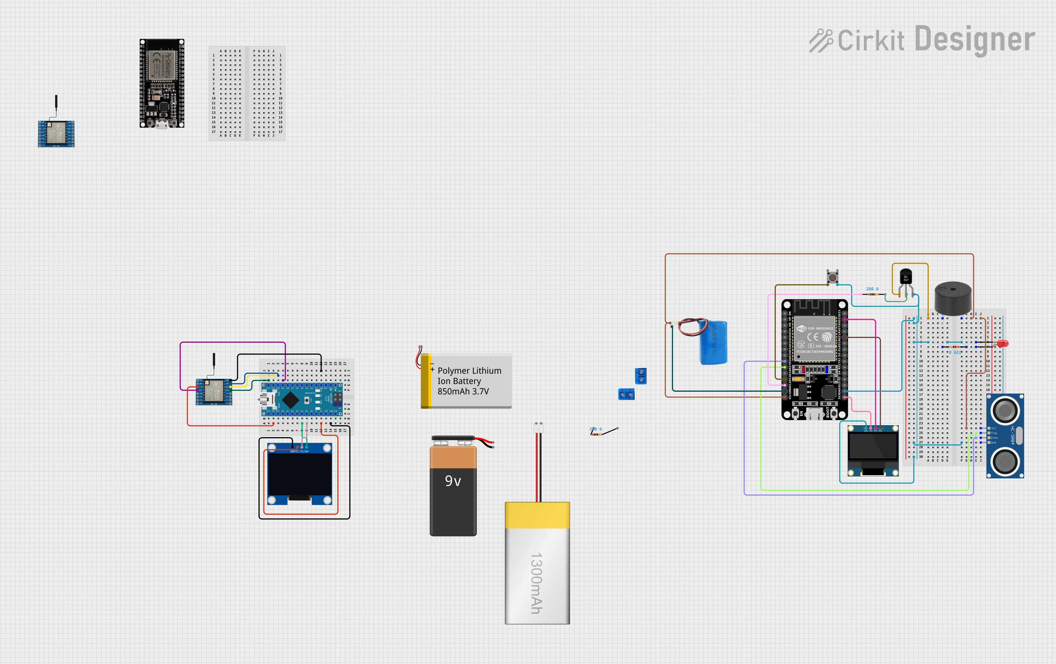
Circuit Documentation
Summary of the Circuit
This circuit integrates various components including microcontrollers, sensors, displays, and communication modules to perform a set of functions. The ESP32 microcontroller serves as the central processing unit, interfacing with a buzzer, an HC-SR04 ultrasonic sensor, an OLED display, and a LoRa communication module. The Arduino Nano is used to interface with another LoRa module and an OLED display. The circuit is powered by a 5V battery and includes a BC547 transistor to control the buzzer. A pushbutton is included for user input, and LEDs are used for visual feedback.
Component List
Microcontrollers
- ESP32 (30 pin): A powerful microcontroller with Wi-Fi and Bluetooth capabilities.
- Arduino Nano: A compact microcontroller board based on the ATmega328P.
Sensors and Modules
- HC-SR04 Ultrasonic Sensor: Measures distance by emitting ultrasonic waves and measuring the time taken for the echo to return.
- LoRa Ra-02 SX1278: A long-range communication module based on the SX1278 chip.
Displays
- 0.96" OLED: A small display for visual output.
- 128x64 OLED Display (I2C IIC SPI Serial): Another small display that can communicate over I2C or SPI.
Power Sources
- 5v battery: Provides power to the circuit.
Actuators
- buzzer: An audible signaling device.
Passive Components
- Resistor: Used to limit current or divide voltages in the circuit.
- LED: Two Pin (red): A red light-emitting diode for visual indication.
Other Components
- BC547 Transistor: A general-purpose NPN transistor used for switching or amplification.
- Pushbutton: A simple switch mechanism for control or input.
Wiring Details
ESP32 (30 pin)
- Vin: Connected to the positive terminal of the 5v battery.
- GND: Common ground with the HC-SR04 Ultrasonic Sensor, BC547 Transistor, Pushbutton, and 0.96" OLED.
- D27: Connected to the TRIG pin of the HC-SR04 Ultrasonic Sensor.
- D26: Connected to the ECHO pin of the HC-SR04 Ultrasonic Sensor.
- D22: Connected to the SCK pin of the 0.96" OLED.
- D21: Connected to the SDA pin of the 0.96" OLED.
- D13: Connected to one pin of a Resistor.
- D12: Connected to Pin 2 (in) of the Pushbutton.
- 3V3: Connected to the VDD pin of the 0.96" OLED.
Arduino Nano
- VIN: Connected to the 5V pin (power input).
- 3V3: Connected to the 3.3V pin of the LoRa Ra-02 SX1278.
- 5V: Connected to the VCC pin of the 128x64 OLED Display and VIN pin (power input).
- GND: Common ground with the LoRa Ra-02 SX1278 and 128x64 OLED Display.
- A4: Connected to the SDA pin of the 128x64 OLED Display.
- A5: Connected to the SCL pin of the 128x64 OLED Display.
- D9: Connected to the RST pin of the LoRa Ra-02 SX1278.
- D10: Connected to the NSS pin of the LoRa Ra-02 SX1278.
- D11/MOSI: Connected to the MOSI pin of the LoRa Ra-02 SX1278.
- D12/MISO: Connected to the MISO pin of the LoRa Ra-02 SX1278.
HC-SR04 Ultrasonic Sensor
- VCC: Connected to the positive terminal of the 5v battery.
- GND: Common ground with the ESP32 (30 pin), BC547 Transistor, Pushbutton, and 0.96" OLED.
- TRIG: Connected to the D27 pin of the ESP32 (30 pin).
- ECHO: Connected to the D26 pin of the ESP32 (30 pin).
LoRa Ra-02 SX1278
- 3.3V: Connected to the 3V3 pin of the Arduino Nano.
- GND: Common ground with the Arduino Nano.
- NSS: Connected to the D10 pin of the Arduino Nano.
- MOSI: Connected to the D11/MOSI pin of the Arduino Nano.
- MISO: Connected to the D12/MISO pin of the Arduino Nano.
- SCK: Connected to the D13/SCK pin of the Arduino Nano.
- RST: Connected to the D9 pin of the Arduino Nano.
0.96" OLED
- VDD: Connected to the 3V3 pin of the ESP32 (30 pin).
- GND: Common ground with the ESP32 (30 pin), HC-SR04 Ultrasonic Sensor, BC547 Transistor, and Pushbutton.
- SCK: Connected to the D22 pin of the ESP32 (30 pin).
- SDA: Connected to the D21 pin of the ESP32 (30 pin).
128x64 OLED Display (I2C IIC SPI Serial)
- VCC: Connected to the 5V pin of the Arduino Nano.
- GND: Common ground with the Arduino Nano.
- SDA: Connected to the A4 pin of the Arduino Nano.
- SCL: Connected to the A5 pin of the Arduino Nano.
BC547 Transistor
- Collector: Connected to the PIN pin of the buzzer.
- Base: Connected to one pin of a Resistor.
- Emitter: Common ground with the ESP32 (30 pin), HC-SR04 Ultrasonic Sensor, Pushbutton, and 0.96" OLED.
Pushbutton
- Pin 2 (in): Connected to the D12 pin of the ESP32 (30 pin).
- Pin 4 (out): Common ground with the ESP32 (30 pin), HC-SR04 Ultrasonic Sensor, BC547 Transistor, and 0.96" OLED.
Resistor
- pin1: Connected to the D13 pin of the ESP32 (30 pin) and the anode pin of the LED.
- pin2: Connected to the Base pin of the BC547 Transistor.
LED: Two Pin (red)
- cathode: Common ground with the ESP32 (30 pin), HC-SR04 Ultrasonic Sensor, BC547 Transistor, Pushbutton, and 0.96" OLED.
- anode: Connected to one pin of a Resistor.
Documented Code
Arduino Nano Code (sketch.ino)
void setup() {
  // put your setup code here, to run once:

}

void loop() {
  // put your main code here, to run repeatedly:

}
Note: The provided code for the Arduino Nano is a template and does not contain any functional code. It needs to be populated with the logic required for the intended operation of the circuit.