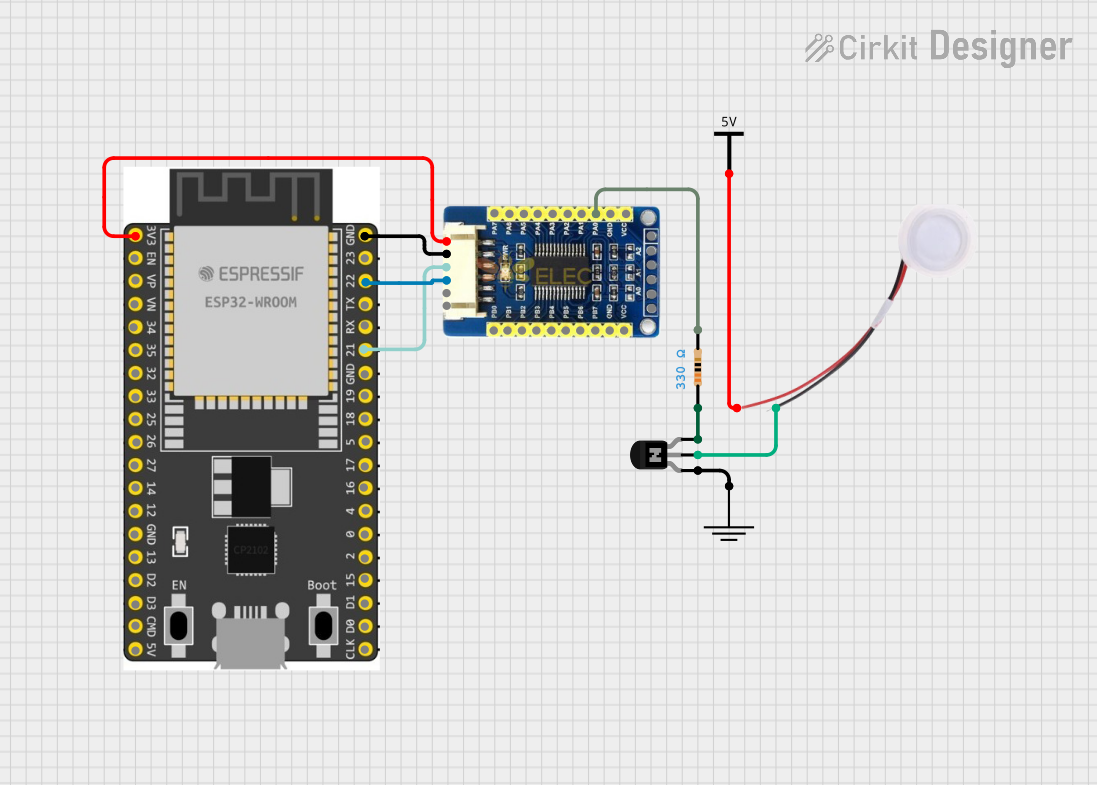
ESP32-Controlled Humidifier with MCP23017 IO Expansion

Circuit Documentation
Summary of the Circuit
This circuit appears to be designed to control a humidifier using an ESP32 Wroom Dev Kit microcontroller in conjunction with an MCP23017 I/O expansion board. The humidifier is powered by an external Vcc source and is switched on and off through an NPN transistor acting as a low-side switch. The base of the transistor is connected to the MCP23017 through a resistor, which likely serves to limit the current flowing into the base. The ESP32 communicates with the MCP23017 via I2C, using GPIO 21 and GPIO 22 for SDA and SCL lines, respectively.
Component List
ESP 32 Wroom Dev Kit
- Microcontroller with WiFi capability.
- Pins: 3V3, EN, VP, VN, GPIO 34, GPIO 35, GPIO 32, GPIO 33, GPIO 25, GPIO 26, GPIO 27, GPIO 14, GND, GPIO 13, SD2, SD3, CMD, V5, GPIO 23, GPIO 22, TXD, RXD, GPIO 21, GPIO 19, GPIO 18, GPIO 5, GPIO 17, GPIO 16, GPIO 4, GPIO 0, GPIO 2, GPIO 15, SD1, SD0, CLK.
MCP23017 I/O Expansion Board
- 16-bit I/O expander with I2C interface.
- Pins: VCC, GND, SDA, SCL, INTA, INTB, PB0-PB7, PA0-PA7.
NPN Transistor (ECB)
- General-purpose NPN transistor for switching applications.
- Pins: Emitter, Collector, Base.
Resistor
- Passive component used to limit current.
- Resistance: 330 Ohms.
GND
- Ground reference for the circuit.
Humidifier
- Device to increase humidity.
- Pins: GND, 5V.
Vcc
- Power supply for the circuit.
Wiring Details
ESP 32 Wroom Dev Kit
- 3V3: Connected to MCP23017 VCC.
- GND: Connected to MCP23017 GND.
- GPIO 22: Connected to MCP23017 SCL.
- GPIO 21: Connected to MCP23017 SDA.
MCP23017 I/O Expansion Board
- VCC: Connected to ESP32 3V3.
- GND: Connected to ESP32 GND.
- SDA: Connected to ESP32 GPIO 21.
- SCL: Connected to ESP32 GPIO 22.
- PA0: Connected to one end of the Resistor.
NPN Transistor (ECB)
- Emitter: Connected to GND.
- Collector: Connected to Humidifier GND.
- Base: Connected to the other end of the Resistor.
Resistor
- Pin1: Connected to NPN Transistor Base.
- Pin2: Connected to MCP23017 PA0.
Humidifier
- 5V: Connected to Vcc.
- GND: Connected to NPN Transistor Collector.
Vcc
- Vcc: Connected to Humidifier 5V.
Documented Code
There is no code provided for the microcontroller. The expected functionality would include initializing the I2C communication with the MCP23017, configuring the MCP23017 ports as outputs, and toggling the appropriate port to control the base of the NPN transistor, thus turning the humidifier on and off.