Arduino UNO and LM358-Based Voltage Monitoring System with Bluetooth Connectivity
Circuit Documentation
Summary
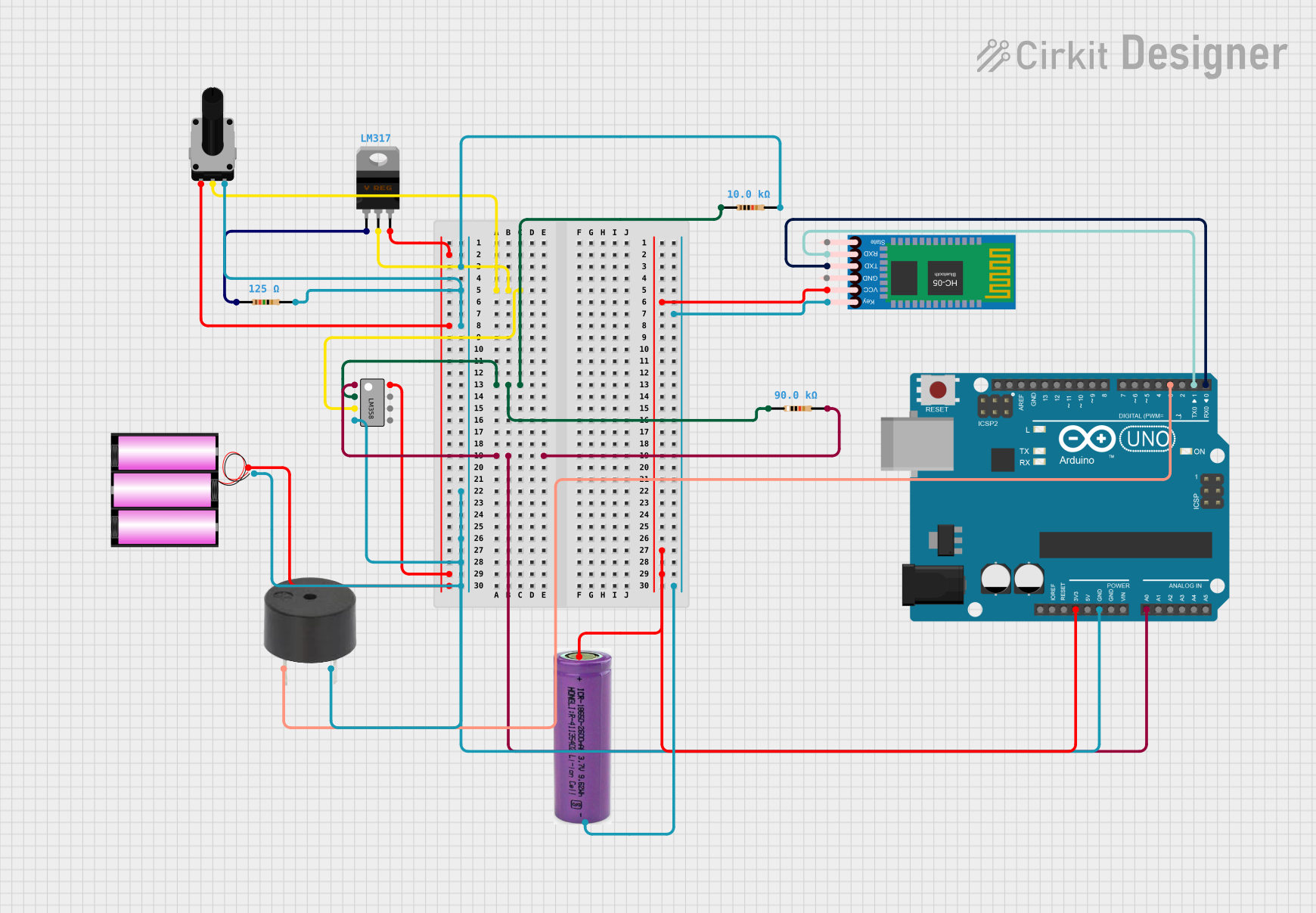
This circuit is designed to monitor voltage levels and provide visual and audible alerts when a certain threshold is exceeded. It includes an LM358 operational amplifier, a set of resistors, a rotary potentiometer, an Arduino UNO microcontroller, an LM317 voltage regulator, a 12V battery, a 3.3V battery, a buzzer, and an HC-05 Bluetooth module. The Arduino UNO is programmed to read the voltage level from the LM358 output, compare it to a predefined threshold, and activate an LED and a buzzer if the threshold is crossed.
Component List
LM358 Operational Amplifier
- Dual operational amplifier used for signal conditioning and amplification.
Resistors
- Various resistors used for setting biasing conditions and voltage division.
Rotary Potentiometer
- Adjustable resistor used for setting the reference voltage level.
Arduino UNO
- Microcontroller board used for processing and control logic.
LM317 Voltage Regulator
- Adjustable voltage regulator used for providing a stable voltage to the circuit.
12V Battery
- Power source for the circuit.
3.3V Battery
- Power source for the HC-05 Bluetooth module.
Buzzer
- Audible alert device activated by the Arduino UNO when the voltage threshold is exceeded.
HC-05 Bluetooth Module
- Wireless communication module for potential remote monitoring or control.
Wiring Details
LM358 Operational Amplifier
- VCC connected to 12V battery.
- VEE, GND connected to the ground net.
- INPUT+ connected to the wiper of the rotary potentiometer.
- INPUT- connected to a 90kΩ resistor.
- OUTPUT 1 connected to the Arduino UNO's A0 pin.
Resistors
- 125Ω resistor connected between the ground net and the rotary potentiometer's leg2.
- 10kΩ resistor connected between the ground net and the rotary potentiometer's leg2.
- 90kΩ resistor connected between the LM358's INPUT- and the Arduino UNO's A0 pin.
Rotary Potentiometer
- Leg1 connected to the LM317 Voltage Regulator's V_out.
- Wiper connected to the LM358's INPUT+.
- Leg2 connected to the ground net.
Arduino UNO
- GND connected to the ground net.
- 3.3V connected to the HC-05 Bluetooth Module's VCC.
- A0 connected to the LM358's OUTPUT 1.
- D3 connected to the buzzer's PIN.
- D1 connected to the HC-05 Bluetooth Module's RXD.
- D0 connected to the HC-05 Bluetooth Module's TXD.
LM317 Voltage Regulator
- V_in connected to the 12V battery.
- V_out connected to the rotary potentiometer's leg1.
- Adj connected to a 125Ω resistor.
12V Battery
- connected to the LM358's VCC and the LM317 Voltage Regulator's V_in.
- connected to the ground net.
3.3V Battery
- connected to the HC-05 Bluetooth Module's VCC.
- connected to the HC-05 Bluetooth Module's Key.
Buzzer
- PIN connected to the Arduino UNO's D3.
- GND connected to the ground net.
HC-05 Bluetooth Module
- VCC connected to the 3.3V battery.
- Key connected to the 3.3V battery's -.
- TXD connected to the Arduino UNO's D0.
- RXD connected to the Arduino UNO's D1.
Documented Code
#include <UnoWiFiDevEd.h>
// Define pin connections
const int voltagePin = A0; // Analog pin to read the voltage
const int ledPin = 2;     // Digital pin to control the LED
const int buzzerPin = 3;  // Digital pin to control the buzzer (optional)

// Define the voltage threshold
const int threshold = 500; // Adjust based on your needs

void setup() {
  pinMode(ledPin, OUTPUT);  // Set LED pin as output
  pinMode(buzzerPin, OUTPUT); // Set buzzer pin as output (optional)
  Serial.begin(9600);       // Initialize serial communication for debugging
}

void loop() {
  // Read the voltage from the measurement circuit
  int voltageReading = analogRead(voltagePin);

  // Print the voltage reading for monitoring
  Serial.print("Voltage Reading: ");
  Serial.println(voltageReading);

  // Check if the voltage exceeds the threshold
  if (voltageReading > threshold) {
    digitalWrite(ledPin, HIGH);   // Turn the LED on
    digitalWrite(buzzerPin, HIGH); // Turn the buzzer on (if used)
  } else {
    digitalWrite(ledPin, LOW);    // Turn the LED off
    digitalWrite(buzzerPin, LOW); // Turn the buzzer off (if used)
  }

  delay(1000);  // Wait for 1 second before the next reading
}
This code is designed to run on an Arduino UNO microcontroller. It reads an analog voltage value from pin A0, which is connected to the output of an LM358 operational amplifier. If the voltage exceeds a predefined threshold, it activates an LED and a buzzer to alert the user. The code also includes serial communication for debugging purposes.