Cirkit Designer
Your all-in-one circuit design IDE
Home /
Project Documentation
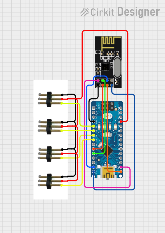
Arduino Nano Controlled NRF24L01 Wireless Communication System
Circuit Documentation
Summary
This circuit integrates an Arduino Nano microcontroller with an NRF24L01 wireless transceiver module and multiple 3-pin male connectors, which are likely used for connecting actuators or sensors that require PWM, ground, and power connections. The Arduino Nano provides control logic and interfaces with the NRF24L01 module to enable wireless communication capabilities. The 3-pin male connectors are interfaced with the Arduino Nano's digital pins and are powered by the 5V output from the Arduino Nano.
Component List
Arduino Nano
- Description: A compact microcontroller board based on the ATmega328P.
- Pins: D1/TX, D0/RX, RESET, GND, D2 to D13, VIN, 5V, A0 to A7, AREF, 3V3.
- Purpose: Acts as the central processing unit of the circuit, running the embedded code and interfacing with other components.
NRF24L01
- Description: A 2.4GHz wireless transceiver module.
- Pins: IRQ (not used), MOSI, CSN, VCC (3V), GND, CE, SCK, MISO.
- Purpose: Provides wireless communication capabilities to the circuit.
3-pin Male Connectors
- Description: Connectors with three pins labeled PWM, gnd, and +vcc.
- Pins: PWM, gnd, +vcc, +VCC out, PWM out, GND out.
- Purpose: Used for connecting external devices that require power, ground, and a PWM signal.
Wiring Details
Arduino Nano
- GND connected to NRF24L01 GND.
- D2 connected to 3-pin male connector PWM (1st instance).
- D3 connected to 3-pin male connector PWM (2nd instance).
- D4 connected to 3-pin male connector PWM (3rd instance).
- D5 connected to 3-pin male connector PWM (4th instance).
- D7 connected to NRF24L01 CE.
- D8 connected to NRF24L01 CSN.
- D11/MOSI connected to NRF24L01 MOSI.
- D12/MISO connected to NRF24L01 MISO.
- 5V connected to all 3-pin male connectors +vcc.
- 3V3 connected to NRF24L01 VCC (3V).
- D13/SCK connected to NRF24L01 SCK.
NRF24L01
- GND connected to Arduino Nano GND.
- CE connected to Arduino Nano D7.
- CSN connected to Arduino Nano D8.
- MOSI connected to Arduino Nano D11/MOSI.
- MISO connected to Arduino Nano D12/MISO.
- VCC (3V) connected to Arduino Nano 3V3.
- SCK connected to Arduino Nano D13/SCK.
3-pin Male Connectors
- PWM connected to Arduino Nano digital pins (D2, D3, D4, D5).
- gnd connected together (common ground).
- +vcc connected to Arduino Nano 5V.
Documented Code
Arduino Nano Code (sketch.ino)
void setup() {
  // put your setup code here, to run once:

}

void loop() {
  // put your main code here, to run repeatedly:

}
Note: The provided code is a template and does not contain any functional logic. It is expected that the user will add the necessary setup and loop code to control the NRF24L01 module and interact with the connected 3-pin male connectors.