
Raspberry Pi 5 Heart Rate and SpO2 Monitor with MAX30102 and OLED Display
View and Edit Project In Cirkit Designer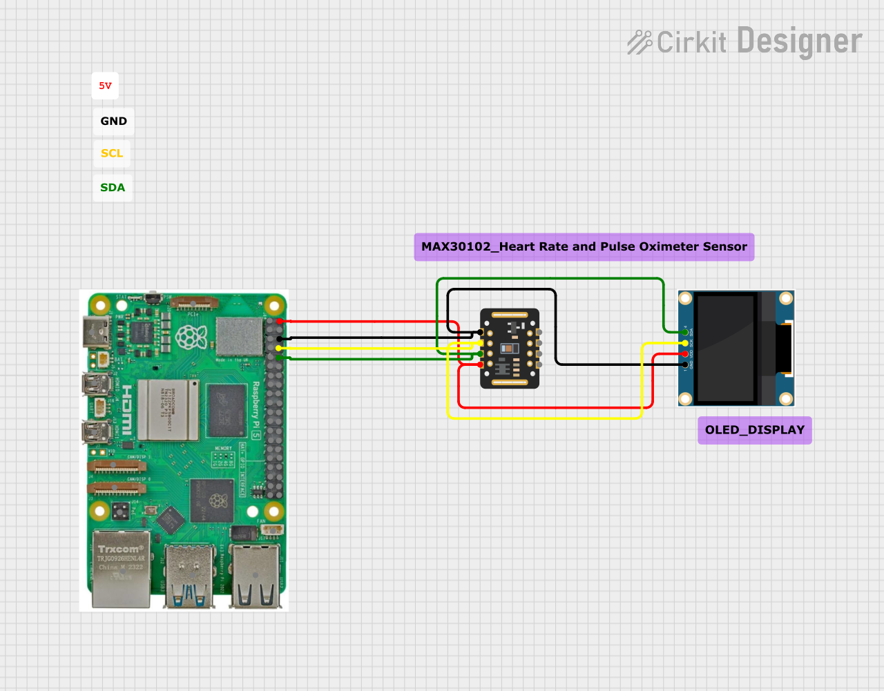
Circuit Documentation
Summary
This circuit integrates a MAX30102 pulse oximeter and heart-rate sensor, a 0.96" OLED display, and a Raspberry Pi 5. The Raspberry Pi 5 serves as the main microcontroller, interfacing with the MAX30102 sensor to read heart rate and SpO2 levels and displaying the readings on the OLED display.
Component List
MAX30102
- Description: Pulse oximeter and heart-rate sensor
- Pins: VIN, SDA, SCL, GND, RD, IRD, INT
0.96" OLED
- Description: OLED display
- Pins: GND, VDD, SCK, SDA
Raspberry Pi 5
- Description: Single-board computer
- Pins: Type-C, Micro HDMI 1, Micro HDMI 2, Camera 1, Camera 2, PoE, Fan, PCIe, USB 3.0, USB 2.0, Ethernet, 5V, GND, 3.3v, GPIO 14, GPIO 15, GPIO 18, GPIO 23, GPIO 24, GPIO 25, GPIO 8, GPIO 7, GPIO 1, GPIO 12, GPIO 16, GPIO 20, GPIO 21, GPIO 2, GPIO 3, GPIO 4, GPIO 17, GPIO 27, GPIO 22, GPIO 10, GPIO 9, GPIO 11, GPIO 0, GPIO 5, GPIO 6, GPIO 13, GPIO 19, GPIO 26
Wiring Details
MAX30102
- GND: Connected to GND of Raspberry Pi 5 and 0.96" OLED
- VIN: Connected to 5V of Raspberry Pi 5 and VDD of 0.96" OLED
- SCL: Connected to GPIO 14 of Raspberry Pi 5 and SCK of 0.96" OLED
- SDA: Connected to GPIO 15 of Raspberry Pi 5 and SDA of 0.96" OLED
0.96" OLED
- GND: Connected to GND of Raspberry Pi 5 and MAX30102
- VDD: Connected to 5V of Raspberry Pi 5 and VIN of MAX30102
- SCK: Connected to GPIO 14 of Raspberry Pi 5 and SCL of MAX30102
- SDA: Connected to GPIO 15 of Raspberry Pi 5 and SDA of MAX30102
Raspberry Pi 5
- GND: Connected to GND of MAX30102 and 0.96" OLED
- 5V: Connected to VIN of MAX30102 and VDD of 0.96" OLED
- GPIO 14: Connected to SCL of MAX30102 and SCK of 0.96" OLED
- GPIO 15: Connected to SDA of MAX30102 and SDA of 0.96" OLED
Documented Code
Raspberry Pi 5 Code
/*
 * This Arduino Sketch reads heart rate, pulse rate, and SpO2 using the MAX30102
 * sensor and displays the readings on a 0.96" OLED display. The Raspberry Pi 5
 * is used as the microcontroller to interface with the sensor and the display.
 */

#include <Wire.h>
#include <Adafruit_GFX.h>
#include <Adafruit_SSD1306.h>
#include "MAX30105.h"
#include "spo2_algorithm.h"

#define SCREEN_WIDTH 128
#define SCREEN_HEIGHT 64
#define OLED_RESET -1
Adafruit_SSD1306 display(SCREEN_WIDTH, SCREEN_HEIGHT, &Wire, OLED_RESET);

MAX30105 particleSensor;

void setup() {
  Wire.begin();
  Serial.begin(115200);

  if (!display.begin(SSD1306_I2C_ADDRESS, OLED_RESET)) {
    Serial.println(F("SSD1306 allocation failed"));
    for (;;);
  }
  display.display();
  delay(2000);
  display.clearDisplay();

  if (!particleSensor.begin(Wire, I2C_SPEED_FAST)) {
    Serial.println(F("MAX30105 was not found. Please check wiring/power."));
    for (;;);
  }
  particleSensor.setup();
  particleSensor.setPulseAmplitudeRed(0x0A);
  particleSensor.setPulseAmplitudeGreen(0);
}

void loop() {
  long irValue = particleSensor.getIR();
  if (checkForBeat(irValue) == true) {
    float beatsPerMinute = 60 / getTimeBetweenBeats();
    float SpO2 = calculateSpO2();

    display.clearDisplay();
    display.setTextSize(1);
    display.setTextColor(SSD1306_WHITE);
    display.setCursor(0, 0);
    display.print(F("Heart Rate: "));
    display.print(beatsPerMinute);
    display.print(F(" BPM"));
    display.setCursor(0, 10);
    display.print(F("SpO2: "));
    display.print(SpO2);
    display.print(F(" %"));
    display.display();
  }
  delay(1000);
}
Additional Code
- Microcontroller 1: Link to Documentation
- Microcontroller 2: No additional code provided.