Cirkit Designer
Your all-in-one circuit design IDE
Home /
Project Documentation
Arduino-Controlled RFM95 Pneumatic Solenoid Valve System
Circuit Documentation
Summary
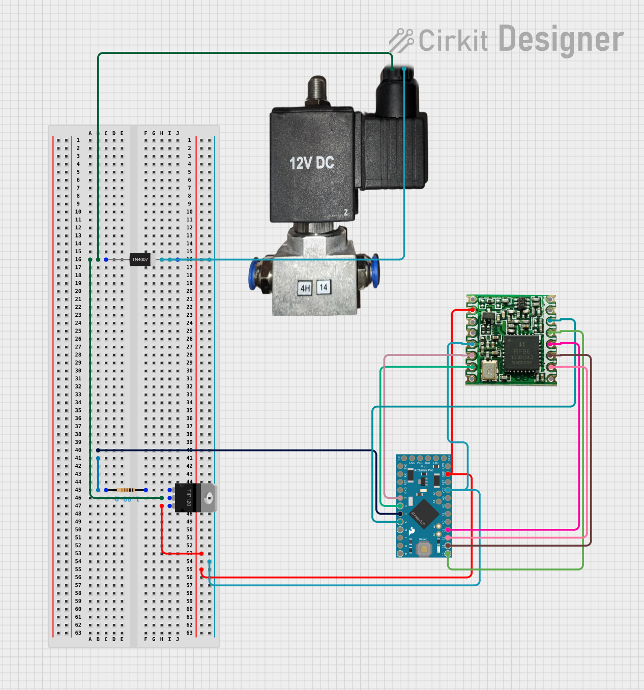
The circuit in question is designed to control a 12v pneumatic solenoid valve using an Arduino Pro Mini microcontroller. The control signal is amplified by a TIP120 Hi-Current Darlington Transistor. A 1N4007 Rectifier Diode is used for back EMF protection. The circuit also includes an RFM95 module for wireless communication, which is interfaced with the Arduino Pro Mini. The Arduino is programmed to switch the solenoid valve on and off at one-second intervals.
Component List
Arduino Pro Mini
- Microcontroller board based on the ATmega328
- Operating Voltage: 3.3V or 5V (depending on the model)
- Digital I/O Pins: 14 (of which 6 provide PWM output)
- Analog Input Pins: 8
- Clock Speed: 8 MHz or 16 MHz
12v Pneumatic Solenoid Valve
- Operates on 12V power supply
- Used for controlling the flow of air or liquid in pneumatic systems
TIP120 Hi-Current Darlington Transistor
- NPN Darlington Transistor
- Collector-Emitter Voltage: 60V
- Collector Current (DC): 5A
1N4007 Rectifier Diode
- Standard silicon rectifier diode
- Peak Repetitive Reverse Voltage: 1000V
- Continuous Forward Current: 1A
Resistor
- Resistance: 1 Ohm
RFM95
- Long-range transceiver module
- Supports FSK, GFSK, MSK, GMSK, LoRaTM, and OOK modulation
- Frequency Range: 868/915MHz
Wiring Details
Arduino Pro Mini
GNDconnected to the ground planeVCCconnected to the 3.3V power supplySCK,MISO,MOSI,D10connected to the corresponding pins on the RFM95 for SPI communicationD5connected to theRESETpin of the RFM95D3connected toDIO1of the RFM95D2connected toDIO0of the RFM95D4is the control pin for the solenoid valve (via the TIP120 transistor)
12v Pneumatic Solenoid Valve
VCCconnected to theCOLLECTORof the TIP120 transistorGNDconnected to the ground plane
TIP120 Hi-Current Darlington Transistor
BASEconnected to a 1 Ohm resistorCOLLECTORconnected to theAnodeof the 1N4007 diode andVCCof the solenoid valveEMITTERconnected to the ground plane
1N4007 Rectifier Diode
Cathodeconnected to the 3.3V power supplyAnodeconnected to theCOLLECTORof the TIP120 transistor
Resistor
pin1connected to theBASEof the TIP120 transistorpin2connected to the control pin (D4) on the Arduino Pro Mini
RFM95
GNDconnected to the ground plane3.3Vconnected to the 3.3V power supplySCK,MISO,MOSI,NSSconnected to the corresponding pins on the Arduino Pro Mini for SPI communicationRESETconnected toD5on the Arduino Pro MiniDIO1connected toD3on the Arduino Pro MiniDIO0connected toD2on the Arduino Pro Mini
Documented Code
// sketch.ino
int solenoidPin = 4; // This is the output pin on the Arduino we are using

void setup() {
  // put your setup code here, to run once:
  pinMode(solenoidPin, OUTPUT); // Sets the pin as an output
}

void loop() {
  // put your main code here, to run repeatedly:
  digitalWrite(solenoidPin, HIGH); // Switch Solenoid ON
  delay(1000); // Wait 1 Second
  digitalWrite(solenoidPin, LOW); // Switch Solenoid OFF
  delay(1000); // Wait 1 Second
}
This code is designed to run on the Arduino Pro Mini. It initializes a digital pin (D4) as an output to control the solenoid valve. In the loop function, it turns the solenoid on for one second, then off for one second, repeating this cycle indefinitely.