
Raspberry Pi Pico Controlled Multi-Motor System with Encoders and L298N Drivers
View and Edit Project In Cirkit Designer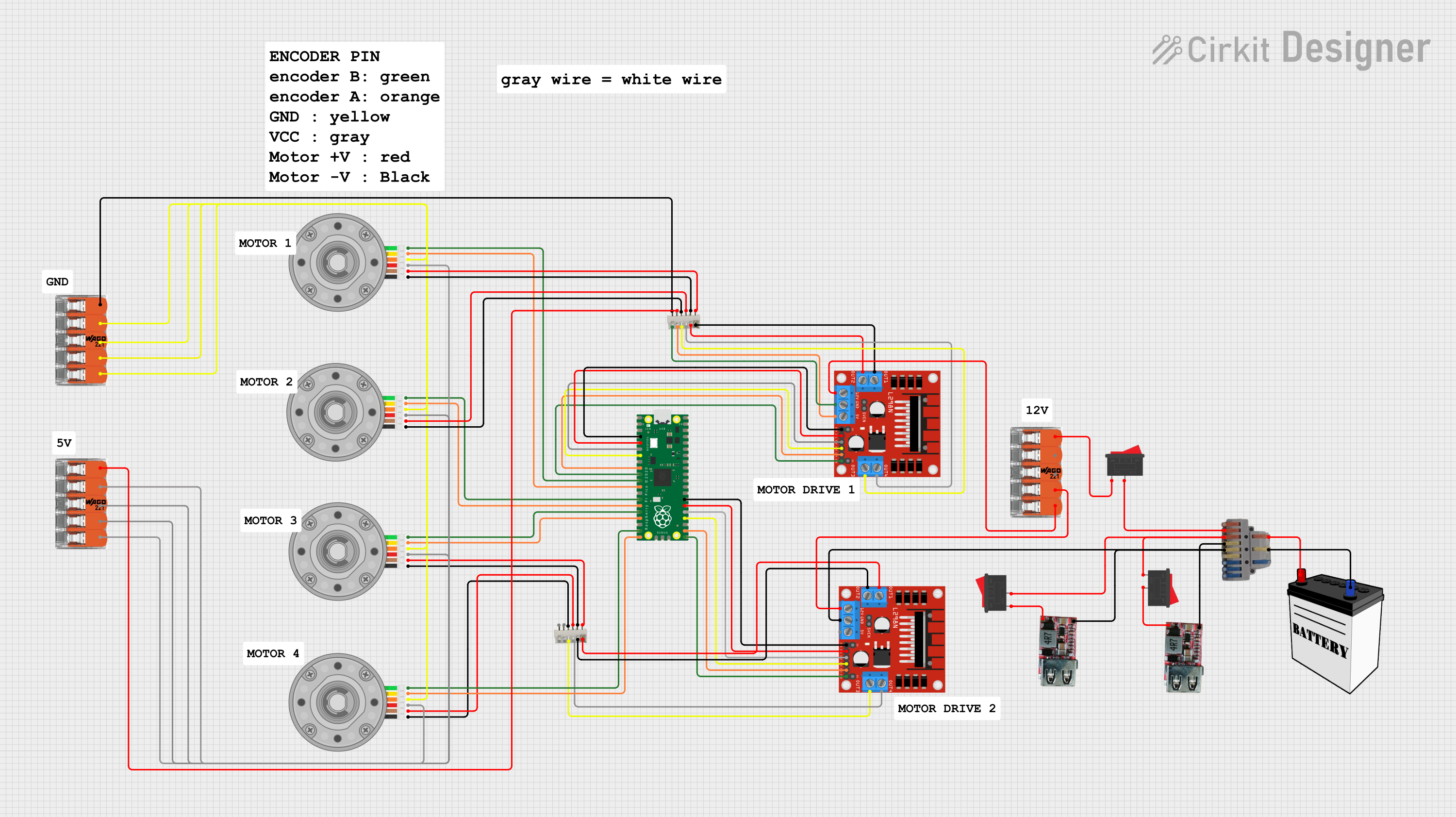
Circuit Documentation
Summary
This circuit is designed to control multiple DC motors with encoders using an L298N DC motor driver module, which is interfaced with a Raspberry Pi Pico microcontroller. The circuit includes power conversion modules to step down voltage from a 12V battery to 5V required by some components. Rocker switches are used to control power flow, and splicing connectors are employed for organizing connections. The Raspberry Pi Pico is programmed to manage the motor's speed and direction while reading encoder signals for feedback.
Component List
DC Motor with Encoder
- Description: A DC motor equipped with an encoder for position feedback.
- Pins: Encoder B, Encoder A, GND, VCC, Motor +ve, Motor -ve
L298N DC Motor Driver
- Description: A motor driver module capable of driving two DC motors. It includes an onboard 5V regulator and provides pins for motor control inputs and outputs.
- Pins: OUT1, OUT2, 12V, GND, 5V, OUT3, OUT4, 5V-ENA-JMP-I, 5V-ENA-JMP-O, +5V-J1, +5V-J2, ENA, IN1, IN2, IN3, IN4, ENB
Raspberry Pi Pico
- Description: A microcontroller board based on the RP2040 microcontroller, featuring a dual-core ARM Cortex-M0+ processor.
- Pins: pin 1 to pin 43
Splicing Connector WAGO 221
- Description: A reusable splicing connector used for easy wiring and organization.
- Pins: Port 1, Port 2, Port 3, Port 4, Port 5
6pin JST Connector
- Description: A connector used for making detachable connections, commonly used for motor and sensor interfaces.
- Pins: Not specified
Rocker Switch
- Description: A switch used to connect or disconnect the electrical circuit.
- Pins: 1, 2
12V to 5V Converter
- Description: A power converter module that steps down the voltage from 12V to 5V.
- Pins: -, +
Pin Connector
- Description: A generic connector for making electrical connections.
- Pins: Not specified
12V Battery
- Description: A power source for the circuit.
- Pins: VCC, GND
Comment
- Description: A placeholder for comments or notes within the circuit design.
- Pins: Not applicable
Wiring Details
DC Motor with Encoder
- Encoder B, Encoder A: Connected to Raspberry Pi Pico for encoder signal reading.
- GND: Connected to Splicing Connector WAGO 221 for ground distribution.
- VCC: Connected to Splicing Connector WAGO 221 for power distribution.
- Motor +ve, Motor -ve: Connected to L298N DC motor driver motor output pins via 6pin JST connectors.
L298N DC Motor Driver
- OUT1, OUT2, OUT3, OUT4: Connected to DC Motor with Encoder motor input pins via 6pin JST connectors.
- 12V: Connected to Splicing Connector WAGO 221 for power input from the battery.
- GND: Connected to 6pin JST connector and pin connector for ground distribution.
- 5V: Connected to 6pin JST connector for providing 5V to other components if needed.
- ENA, ENB: Connected to Raspberry Pi Pico for enabling motor channels.
- IN1, IN2, IN3, IN4: Connected to Raspberry Pi Pico for controlling motor direction.
Raspberry Pi Pico
- pin 4, pin 5, pin 6, pin 7, pin 9, pin 10, pin 11, pin 12, pin 14, pin 15, pin 16, pin 17, pin 19, pin 20, pin 21, pin 22, pin 24, pin 25, pin 26, pin 27: Connected to L298N DC motor driver for motor control and encoder signal reading.
Splicing Connector WAGO 221
- Port 1, Port 2, Port 3, Port 4, Port 5: Used for distributing power and ground connections among various components.
6pin JST Connector
- Used for making detachable connections between DC motors and motor drivers.
Rocker Switch
- Used to control the power flow from the battery to the circuit.
12V to 5V Converter
- Used to step down the voltage from 12V to 5V for components requiring lower voltage.
Pin Connector
- Used for making connections between the battery, rocker switch, and 12V to 5V converter.
12V Battery
- Provides the power source for the entire circuit.
Documented Code
void setup() {
  // put your setup code here, to run once:

}

void loop() {
  // put your main code here, to run repeatedly:

}
Filename: sketch.ino
Description: This is the main code file for the Raspberry Pi Pico microcontroller. The setup() function is called once when the microcontroller is powered on or reset. The loop() function is called repeatedly and contains the main logic for motor control and encoder feedback. The actual implementation details are not provided in the given code snippet and would need to be developed based on the specific requirements of the motor control application.