
Battery-Powered Temperature-Sensitive LED and Buzzer Circuit with NTC Thermistor and BC547 Transistor
View and Edit Project In Cirkit Designer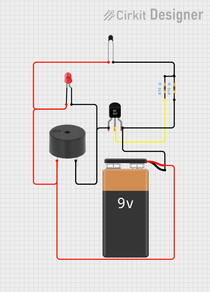
Circuit Documentation
Summary
This document provides a detailed description of a circuit that includes a temperature sensor (NTC), a red LED, a buzzer, a BC547 transistor, resistors, and a 9V battery. The circuit is designed to monitor temperature and provide visual and auditory alerts.
Component List
NTC (Negative Temperature Coefficient Thermistor)
- Pins: A0, A1
- Description: A thermistor used to measure temperature. Its resistance decreases as the temperature increases.
LED: Two Pin (red)
- Pins: Cathode, Anode
- Description: A red light-emitting diode used for visual indication.
Buzzer
- Pins: PIN, GND
- Description: An electronic device that produces sound when a voltage is applied.
BC547 Transistor
- Pins: Collector, Base, Emitter
- Description: A general-purpose NPN transistor used for switching and amplification.
Resistor (470 Ohms)
- Pins: Pin1, Pin2
- Description: A resistor with a resistance of 470 Ohms used to limit current.
9V Battery
- Pins: -, +
- Description: A power source providing 9V DC.
Wiring Details
NTC (Negative Temperature Coefficient Thermistor)
A0 is connected to:
- Cathode of the red LED
- PIN of the buzzer
- Positive terminal of the 9V battery
A1 is connected to:
- Pin2 of the first 470 Ohm resistor
- Pin2 of the second 470 Ohm resistor
LED: Two Pin (red)
Cathode is connected to:
- A0 of the NTC
- PIN of the buzzer
- Positive terminal of the 9V battery
Anode is connected to:
- Collector of the BC547 transistor
- GND of the buzzer
Buzzer
PIN is connected to:
- Cathode of the red LED
- A0 of the NTC
- Positive terminal of the 9V battery
GND is connected to:
- Anode of the red LED
- Collector of the BC547 transistor
BC547 Transistor
Collector is connected to:
- Anode of the red LED
- GND of the buzzer
Base is connected to:
- Pin1 of the first 470 Ohm resistor
Emitter is connected to:
- Pin1 of the second 470 Ohm resistor
- Negative terminal of the 9V battery
Resistor (470 Ohms)
First Resistor:
Pin1 is connected to:
- Base of the BC547 transistor
Pin2 is connected to:
- A1 of the NTC
- Pin2 of the second 470 Ohm resistor
Second Resistor:
Pin1 is connected to:
- Emitter of the BC547 transistor
- Negative terminal of the 9V battery
Pin2 is connected to:
- A1 of the NTC
- Pin2 of the first 470 Ohm resistor
9V Battery
Positive (+) is connected to:
- Cathode of the red LED
- PIN of the buzzer
- A0 of the NTC
Negative (-) is connected to:
- Pin1 of the second 470 Ohm resistor
- Emitter of the BC547 transistor
Code
There is no code associated with this circuit.