
Arduino UNO Smart Light Control with Bluetooth and Photocell
View and Edit Project In Cirkit Designer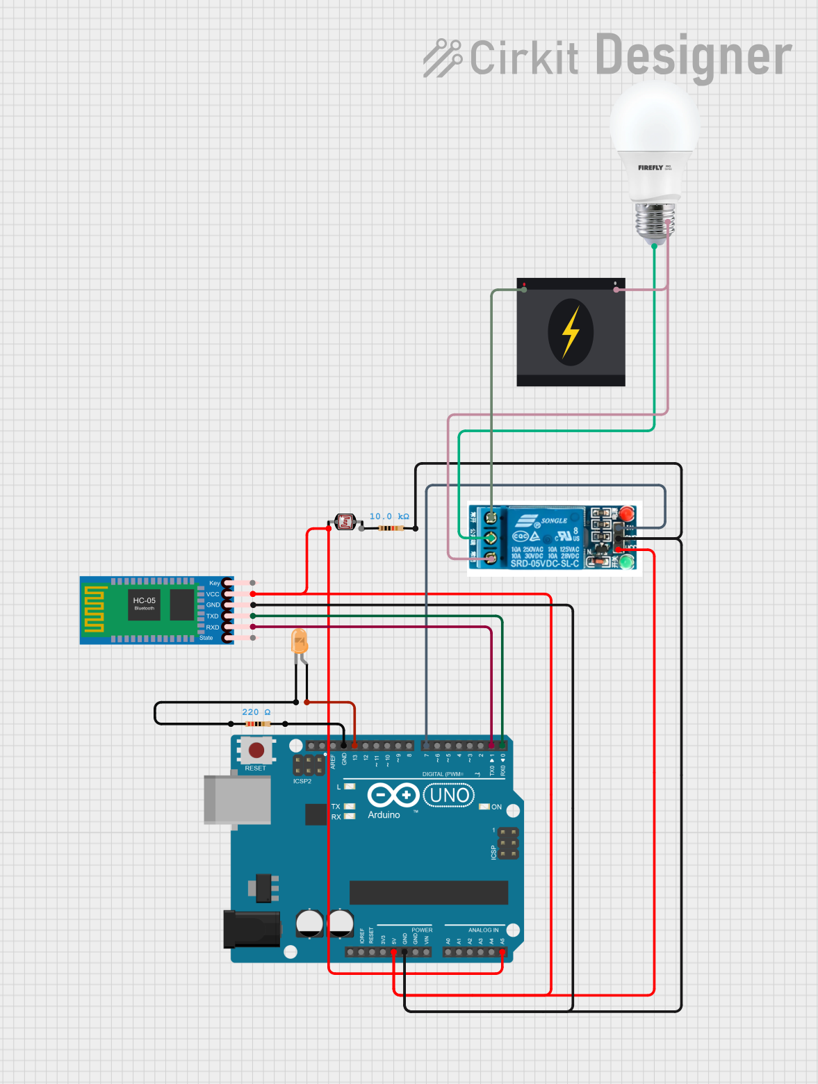
Circuit Documentation
Summary
This circuit involves an Arduino UNO microcontroller, a photocell (LDR), an HC-05 Bluetooth module, a 5V relay, resistors, an LED, and a bulb connected to a 240V power source. The circuit is designed to control the bulb using the relay, with inputs from the photocell and Bluetooth module. The LED is used as an indicator.
Component List
Arduino UNO
- Description: A microcontroller board based on the ATmega328P.
- Pins: UNUSED, IOREF, Reset, 3.3V, 5V, GND, Vin, A0, A1, A2, A3, A4, A5, SCL, SDA, AREF, D13, D12, D11, D10, D9, D8, D7, D6, D5, D4, D3, D2, D1, D0
Photocell (LDR)
- Description: A light-dependent resistor used to detect light levels.
- Pins: pin 0, pin 1
HC-05 Bluetooth Module
- Description: A Bluetooth module used for wireless communication.
- Pins: Key, VCC, TXD, RXD, State, GND
5V Relay
- Description: An electromechanical switch used to control high voltage devices.
- Pins: Normally Open, Common terminal, Normally Closed, In, GND, VCC
Resistor (10k Ohms)
- Description: A resistor with a resistance of 10k Ohms.
- Pins: pin1, pin2
LED: Two Pin (orange)
- Description: An orange LED used as an indicator.
- Pins: cathode, anode
Resistor (220 Ohms)
- Description: A resistor with a resistance of 220 Ohms.
- Pins: pin1, pin2
Bulb
- Description: A standard bulb.
- Pins: +, -
240V Power Source
- Description: A power source providing 240V AC.
- Pins: Live, Neutral
Wiring Details
Arduino UNO
- 5V connected to Photocell (LDR) pin 0, 5V Relay VCC, HC-05 Bluetooth Module VCC
- GND connected to 5V Relay GND, Resistor (10k Ohms) pin2, HC-05 Bluetooth Module GND, Resistor (220 Ohms) pin2
- A5 connected to Photocell (LDR) pin 0
- D13 connected to LED anode
- D7 connected to 5V Relay In
- D1 connected to HC-05 Bluetooth Module RXD
- D0 connected to HC-05 Bluetooth Module TXD
Photocell (LDR)
- pin 0 connected to Arduino UNO 5V, Arduino UNO A5
- pin 1 not connected
HC-05 Bluetooth Module
- VCC connected to Arduino UNO 5V
- GND connected to Arduino UNO GND
- TXD connected to Arduino UNO D0
- RXD connected to Arduino UNO D1
5V Relay
- VCC connected to Arduino UNO 5V
- GND connected to Arduino UNO GND
- In connected to Arduino UNO D7
- Normally Open connected to 240V Power Source Live
- Common terminal connected to Bulb +
- Normally Closed connected to 240V Power Source Neutral, Bulb -
Resistor (10k Ohms)
- pin1 not connected
- pin2 connected to Arduino UNO GND
LED: Two Pin (orange)
- anode connected to Arduino UNO D13
- cathode connected to Resistor (220 Ohms) pin1
Resistor (220 Ohms)
- pin1 connected to LED cathode
- pin2 connected to Arduino UNO GND
Bulb
- + connected to 5V Relay Common terminal
- - connected to 240V Power Source Neutral, 5V Relay Normally Closed
240V Power Source
- Live connected to 5V Relay Normally Open
- Neutral connected to Bulb -, 5V Relay Normally Closed
Code Documentation
Arduino UNO Code
void setup() {
  // put your setup code here, to run once:

}

void loop() {
  // put your main code here, to run repeatedly:

}
This code is a basic template for the Arduino UNO. The setup() function is used to initialize any settings or configurations, and the loop() function contains the main code that runs repeatedly. Currently, both functions are empty and need to be filled with the appropriate logic for the circuit's operation.