Cirkit Designer
Your all-in-one circuit design IDE
Home /
Project Documentation
Arduino Mega 2560-Based Real-Time Clock and LCD Display with Pushbutton Control
Circuit Documentation
Summary
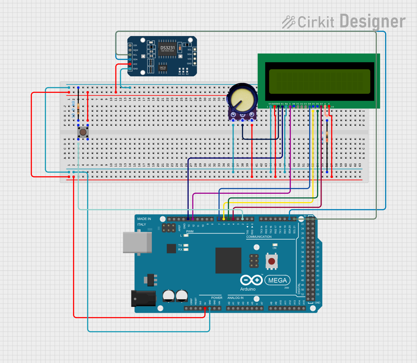
This circuit involves an Arduino Mega 2560 microcontroller interfaced with a 16x2 LCD display, a DS3231 RTC module, a pushbutton, a potentiometer, and resistors. The circuit is designed to demonstrate basic input and output operations, including reading from a pushbutton and potentiometer, displaying information on an LCD, and keeping track of time using the RTC module.
Component List
Arduino Mega 2560
- Description: A microcontroller board based on the ATmega2560.
- Pins: IOREF, RESET, 3V3, 5V, GND, VIN, A0-A15, D0-D53, AREF, SDA, SCL
16x2 LCD
- Description: A 16x2 character LCD display.
- Pins: VSS, VDD, V0, RS, RW, E, D0-D7, A, K
Resistor (220 Ohms)
- Description: A resistor with a resistance of 220 Ohms.
- Pins: pin1, pin2
Resistor (10k Ohms)
- Description: A resistor with a resistance of 10k Ohms.
- Pins: pin1, pin2
Pushbutton
- Description: A simple pushbutton switch.
- Pins: Pin 1 (in), Pin 2 (in), Pin 3 (out), Pin 4 (out)
Potentiometer
- Description: A variable resistor (potentiometer).
- Pins: GND, Output, VCC
DS3231 RTC
- Description: A real-time clock module.
- Pins: 32K, SQW, SCL, SDA, VCC, GND
Wiring Details
Arduino Mega 2560
- D2 PWM: Connected to Pushbutton Pin 2 (in)
- 5V: Connected to Pushbutton Pin 3 (out), DS3231 RTC VCC, Potentiometer VCC, 16x2 LCD VDD, 16x2 LCD K
- GND: Connected to Potentiometer GND, Resistor (220 Ohms) pin1, 16x2 LCD VSS, Resistor (10k Ohms) pin2, 16x2 LCD RW, DS3231 RTC GND
- D21/SCL: Connected to DS3231 RTC SCL
- D20/SDA: Connected to DS3231 RTC SDA
- D4 PWM: Connected to 16x2 LCD D7
- D5 PWM: Connected to 16x2 LCD D6
- D6 PWM: Connected to 16x2 LCD D5
- D7 PWM: Connected to 16x2 LCD D4
- D12 PWM: Connected to 16x2 LCD E
- D13 PWM: Connected to 16x2 LCD RS
16x2 LCD
- VSS: Connected to Arduino Mega 2560 GND
- VDD: Connected to Arduino Mega 2560 5V
- V0: Connected to Potentiometer Output
- RS: Connected to Arduino Mega 2560 D13 PWM
- RW: Connected to Arduino Mega 2560 GND
- E: Connected to Arduino Mega 2560 D12 PWM
- D4: Connected to Arduino Mega 2560 D7 PWM
- D5: Connected to Arduino Mega 2560 D6 PWM
- D6: Connected to Arduino Mega 2560 D5 PWM
- D7: Connected to Arduino Mega 2560 D4 PWM
- A: Connected to Resistor (220 Ohms) pin2
- K: Connected to Arduino Mega 2560 5V
Resistor (220 Ohms)
- pin1: Connected to Arduino Mega 2560 GND
- pin2: Connected to 16x2 LCD A
Resistor (10k Ohms)
- pin1: Connected to Pushbutton Pin 1 (in)
- pin2: Connected to Arduino Mega 2560 GND
Pushbutton
- Pin 1 (in): Connected to Resistor (10k Ohms) pin1
- Pin 2 (in): Connected to Arduino Mega 2560 D2 PWM
- Pin 3 (out): Connected to Arduino Mega 2560 5V
- Pin 4 (out): Not connected
Potentiometer
- GND: Connected to Arduino Mega 2560 GND
- Output: Connected to 16x2 LCD V0
- VCC: Connected to Arduino Mega 2560 5V
DS3231 RTC
- SCL: Connected to Arduino Mega 2560 D21/SCL
- SDA: Connected to Arduino Mega 2560 D20/SDA
- VCC: Connected to Arduino Mega 2560 5V
- GND: Connected to Arduino Mega 2560 GND
Code Documentation
Arduino Mega 2560 Code
File Name: sketch.ino
void setup() {
  // put your setup code here, to run once:

}

void loop() {
  // put your main code here, to run repeatedly:

}
File Name: documentation.txt
This code is a basic template for the Arduino Mega 2560. The setup function is where you initialize your components and settings, and the loop function is where you place the main logic that runs repeatedly.