
ESP32-Controlled Robotic Vehicle with UV Detection and Distance Sensing
View and Edit Project In Cirkit Designer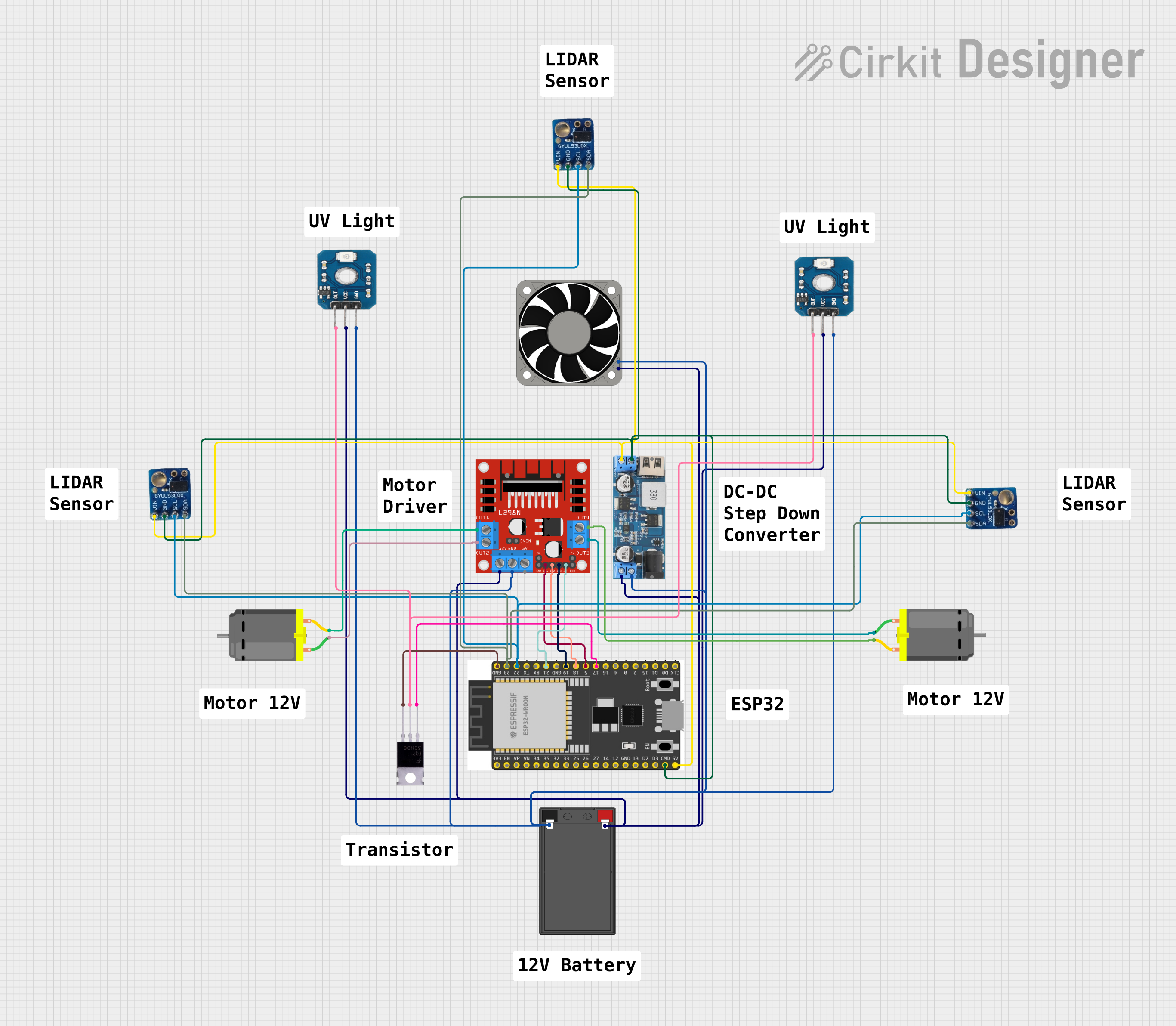
Circuit Documentation
Summary
This circuit is designed to control two DC motors using an ESP32 microcontroller and an L298N motor driver. It also includes a step-down power converter to provide 5V power to the ESP32 and other 5V components. The circuit is powered by a 12V 7Ah battery, which also powers a 12V fan and UV sensors. The ESP32 reads data from multiple VL53L0X sensors via I2C communication and controls the motors and a MOSFET, which is connected to UV sensors for some form of output control.
Component List
ESP 32 Wroom Dev Kit
- Microcontroller development board based on the ESP32 chip.
- Provides WiFi and Bluetooth connectivity.
- Features multiple GPIO pins for interfacing with sensors and actuators.
12v to 5v Step Down Power Converter
- Converts input voltages ranging from 9V to 36V to a stable 5V output.
- Used to power 5V components in the circuit, including the ESP32.
L298N DC Motor Driver
- An H-bridge motor driver capable of driving a pair of DC motors.
- Provides speed and direction control for the motors.
DC Motor (x2)
- Electric motors that convert electrical energy into mechanical motion.
- Controlled by the L298N motor driver.
12v 7ah Battery
- Provides the main power source for the circuit.
- Powers the 12V components directly and provides input to the step-down converter.
UV Sensor (x2)
- Sensors that detect the intensity of ultraviolet light.
- Their output is presumably used to control the MOSFET.
VL53L0X (x3)
- Time-of-flight (ToF) laser-ranging sensor modules.
- Provide accurate distance measurements via I2C communication.
40mm Fan 12v
- A 12V cooling fan.
- Used to dissipate heat from components or the environment.
Mosfet
- A type of transistor used for switching electronic signals.
- In this circuit, it is likely used to switch higher current loads, such as the UV sensors.
Wiring Details
ESP 32 Wroom Dev Kit
3V3: Not connected.EN: Not connected.VP: Not connected.VN: Not connected.GPIO 34: Not connected.GPIO 35: Not connected.GPIO 32: Not connected.GPIO 33: Not connected.GPIO 25: Not connected.GPIO 26: Not connected.GPIO 27: Not connected.GPIO 14: Not connected.GND: Connected to the GND of the step-down converter, VL53L0X sensors, and the source of the MOSFET.GPIO 13: Not connected.SD2: Not connected.SD3: Not connected.CMD: Connected to the GND of the step-down converter.V5: Connected to the 5V output of the step-down converter.GPIO 23: Connected to the SDA line of the VL53L0X sensors.GPIO 22: Connected to the SCL line of the VL53L0X sensors.TXD: Not connected.RXD: Not connected.GPIO 21: Connected to IN4 of the L298N motor driver.GPIO 19: Connected to IN3 of the L298N motor driver.GPIO 18: Connected to IN2 of the L298N motor driver.GPIO 5: Connected to IN1 of the L298N motor driver.GPIO 17: Connected to the gate of the MOSFET.GPIO 16: Not connected.GPIO 4: Not connected.GPIO 0: Not connected.GPIO 2: Not connected.GPIO 15: Not connected.SD1: Not connected.SD0: Not connected.CLK: Not connected.
12v to 5v Step Down Power Converter
VIN 9v-36v: Not connected.VIN+: Connected to the 12V - of the battery.VIN-: Connected to the 12V + of the battery.USB OUTPUT 5V: Not connected.5v OUTPUT: Connected to the V5 of the ESP32 and VIN of the VL53L0X sensors.GND: Connected to the GND of the ESP32 and VL53L0X sensors.
L298N DC Motor Driver
OUT1: Connected to pin 2 of one DC motor.OUT2: Connected to pin 1 of the same DC motor.12V: Connected to the 12V + of the battery.GND: Connected to the 12V - of the battery.5V: Not connected.OUT3: Connected to pin 1 of the other DC motor.OUT4: Connected to pin 2 of the other DC motor.5V-ENA-JMP-I: Not connected.5V-ENA-JMP-O: Not connected.+5V-J1: Not connected.+5V-J2: Not connected.ENA: Not connected.IN1: Connected to GPIO 5 of the ESP32.IN2: Connected to GPIO 18 of the ESP32.IN3: Connected to GPIO 19 of the ESP32.IN4: Connected to GPIO 21 of the ESP32.ENB: Not connected.
DC Motor
pin 1: Connected to OUT2 or OUT3 of the L298N motor driver, depending on the motor instance.pin 2: Connected to OUT1 or OUT4 of the L298N motor driver, depending on the motor instance.
12v 7ah Battery
12v +: Connected to the 12V input of the L298N motor driver, 12V + of the fan, and VIN- of the step-down converter.12v -: Connected to the GND of the L298N motor driver, 12V - of the fan, and VIN+ of the step-down converter.
UV Sensor
OUT: Connected to the drain of the MOSFET.vcc: Connected to the 12V + of the battery.GND: Connected to the 12V - of the battery.
VL53L0X
vin: Connected to the 5V output of the step-down converter.gnd: Connected to the GND of the ESP32 and step-down converter.scl: Connected to GPIO 22 of the ESP32.sda: Connected to GPIO 23 of the ESP32.
40mm Fan 12v
+12V: Connected to the 12V + of the battery.-12V: Connected to the 12V - of the battery.
Mosfet
Gate: Connected to GPIO 17 of the ESP32.Drain: Connected to the OUT of the UV sensors.Source: Connected to the GND of the ESP32.
Documented Code
No code was provided for the microcontrollers in the circuit. Therefore, this section is left blank until code is available for documentation.