
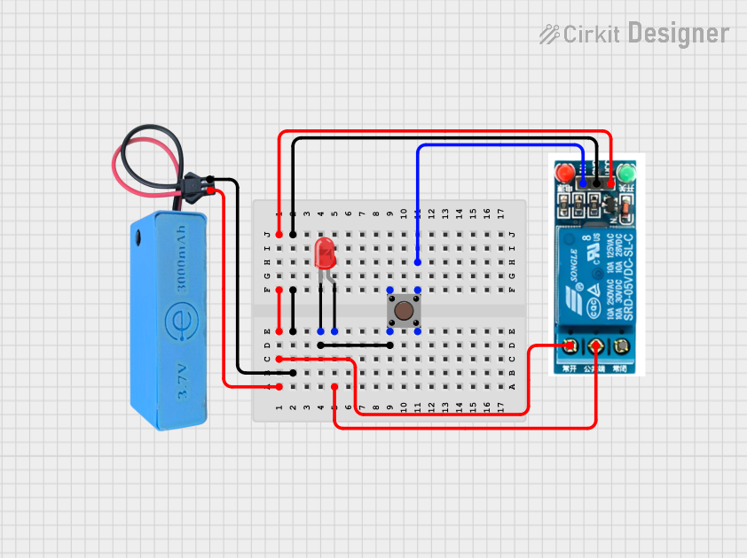
Circuit Documentation
Summary
This circuit consists of a microcontroller, a relay, an LED, and a pushbutton. The microcontroller powers the relay, which in turn controls the LED. The pushbutton is used to trigger the relay, allowing current to flow through the LED, thereby illuminating it.
Component List
MAHIR 1.mini
- Pins: GND, 3.7v
- Description: A microcontroller used to control the relay.
- Purpose in Circuit: Provides power to the relay.
LED: Two Pin (red)
- Pins: cathode, anode
- Description: A red LED.
- Purpose in Circuit: Illuminates when the relay is activated.
Pushbutton
- Pins: Pin 1 (in), Pin 2 (in), Pin 3 (out), Pin 4 (out)
- Description: A pushbutton switch.
- Purpose in Circuit: Used to trigger the relay.
5v relay
- Pins: Normally Open, Common terminal, Normally Closed, In, GND, VCC
- Description: A relay that controls the LED.
- Purpose in Circuit: Switches the LED on and off based on the pushbutton input.
Wiring Details
MAHIR 1.mini
3.7v is connected to:
- Normally Open pin of the 5v relay
- VCC pin of the 5v relay
GND is connected to:
- GND pin of the 5v relay
LED: Two Pin (red)
cathode is connected to:
- Pin 2 (in) of the Pushbutton
anode is connected to:
- Common terminal of the 5v relay
Pushbutton
Pin 2 (in) is connected to:
- cathode of the LED
Pin 3 (out) is connected to:
- In pin of the 5v relay
5v relay
Normally Open is connected to:
- 3.7v pin of the MAHIR 1.mini
Common terminal is connected to:
- anode of the LED
In is connected to:
- Pin 3 (out) of the Pushbutton
GND is connected to:
- GND pin of the MAHIR 1.mini
VCC is connected to:
- 3.7v pin of the MAHIR 1.mini
Code
There is no code provided for this circuit.