
ESP32-Controlled Smart Device with RFID, LCD, and Relay Modules
View and Edit Project In Cirkit Designer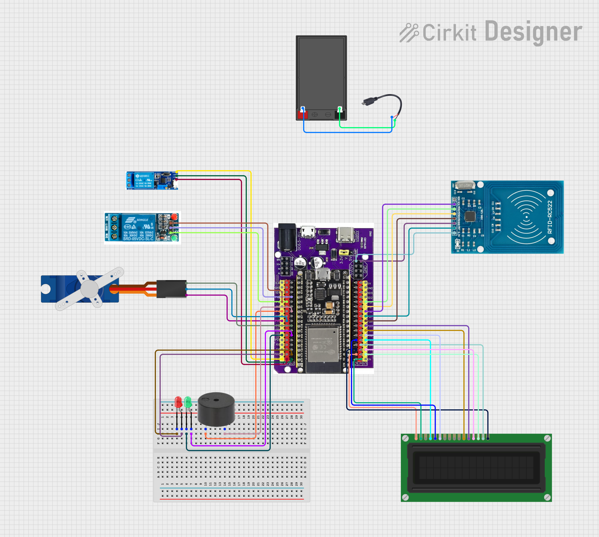
Circuit Documentation
Summary
This circuit integrates various components controlled by an ESP32 microcontroller. The circuit includes LEDs, an LCD display, an RFID-RC522 module, a 5V relay, a servo motor, a buzzer, and a relay module. The ESP32 microcontroller interfaces with these components to control their behavior based on programmed logic. The circuit is powered by a battery connected through a Micro USB to Cable connector. The components are wired to the ESP32's GPIO pins and power lines, enabling interaction and control through embedded software. However, no code has been provided for the microcontroller, indicating that the circuit's functionality is yet to be programmed.
Component List
LED: Two Pin (red)
- Description: A red LED with an anode and cathode pin.
LED: Two Pin (green)
- Description: A green LED with an anode and cathode pin.
LCD Display (16 pin)
- Description: A 16-pin LCD display for visual output.
Esp32 on Baseboard
- Description: A microcontroller with a variety of GPIO pins for controlling various components.
RFID-RC522
- Description: An RFID reader/writer module.
5v relay
- Description: A relay for switching higher power loads.
Tower Pro SG90 servo
- Description: A small servo motor for precise angular movement.
Relay module 5v-30v
- Description: A relay module capable of handling a wide range of voltages.
Buzzer
- Description: An electronic buzzer for audible output.
Micro USB to Cable (2 Pin)
- Description: A connector for power input via Micro USB.
Battery
- Description: A power source for the circuit.
Wiring Details
LED: Two Pin (red)
- Cathode connected to ESP32 Ground (G)
- Anode connected to ESP32 GPIO22
LED: Two Pin (green)
- Cathode connected to ESP32 GPIO19
- Anode connected to ESP32 Ground (G)
LCD Display (16 pin)
- VSS connected to ESP32 Ground (G)
- VDD connected to ESP32 Voltage (V)
- VO not connected
- RS connected to ESP32 GPIO35
- R/W connected to ESP32 Ground (G)
- E connected to ESP32 GPIO32
- DB0-DB3 not connected
- DB4 connected to ESP32 GPIO33
- DB5 connected to ESP32 GPIO25
- DB6 connected to ESP32 GPIO39
- DB7 connected to ESP32 GPIO36
- A connected to ESP32 Voltage (V)
- K connected to ESP32 Ground (G)
Esp32 on Baseboard
- Various GPIOs connected to other components as detailed above.
RFID-RC522
- VCC (3.3V) connected to ESP32 3V
- RST connected to ESP32 GPIO27
- GND connected to ESP32 Ground (GND)
- IRQ connected to ESP32 GPIO26
- MISO connected to ESP32 GPIO12
- MOSI connected to ESP32 GPIO13
- SCK connected to ESP32 GPIO14
- SDA not connected
5v relay
- In connected to ESP32 GPIO2
- GND connected to ESP32 Ground (G)
- VCC connected to ESP32 Voltage (V)
Tower Pro SG90 servo
- Signal connected to ESP32 GPIO17
- +5V connected to ESP32 Voltage (V)
- GND connected to ESP32 Ground (G)
Relay module 5v-30v
- Trigger connected to ESP32 GPIO23
- V+ connected to ESP32 Voltage (V)
- V- connected to ESP32 Ground (G)
Buzzer
- PIN connected to ESP32 GPIO4
- GND connected to ESP32 Ground (G)
Micro USB to Cable (2 Pin)
- Micro USB not connected
-
- connected to Battery +
-
- connected to Battery -
Battery
-
- connected to Micro USB to Cable +
-
- connected to Micro USB to Cable -
Documented Code
No code has been provided for the microcontroller. The functionality of the circuit will be determined by the embedded software that needs to be developed and uploaded to the ESP32 microcontroller. The code will define how the ESP32 interacts with the connected components, such as reading RFID tags, displaying information on the LCD, controlling the relay and servo, and providing audible alerts with the buzzer.