ESP32-Controlled Ultrasonic Distance Measurement with Servo and LCD Display

Circuit Documentation
Summary
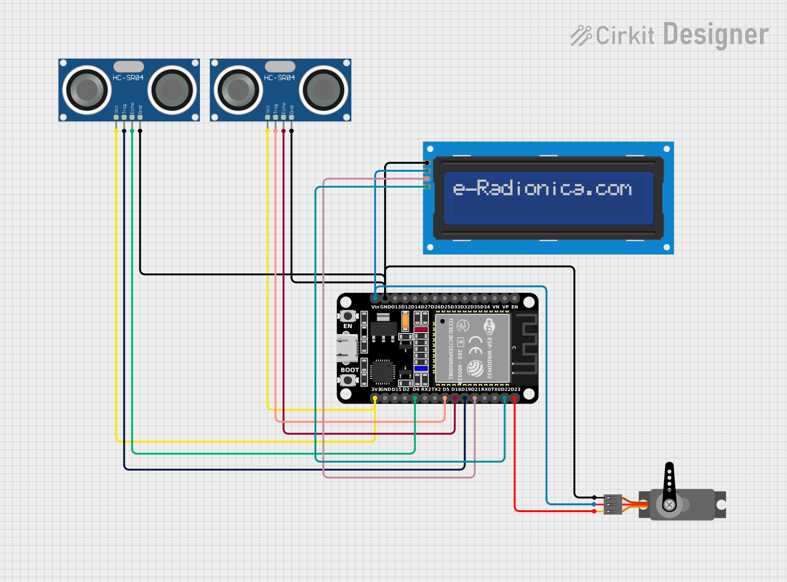
This circuit integrates an ESP32 microcontroller with a 16x2 LCD screen via I2C, two HC-SR04 ultrasonic sensors, and a servo motor. The ESP32 is responsible for controlling the servo motor based on distance measurements from the ultrasonic sensors and displaying information on the LCD screen. The ultrasonic sensors are used to measure distances, and the servo motor is controlled based on these measurements. The LCD screen displays relevant information to the user.
Component List
ESP32 (30 pin)
- Description: A microcontroller with Wi-Fi and Bluetooth capabilities, featuring a wide range of GPIO pins.
- Purpose: Acts as the central processing unit of the circuit, controlling the LCD, ultrasonic sensors, and servo motor.
LCD screen 16x2 I2C
- Description: An alphanumeric liquid crystal display capable of displaying 16 characters per line across 2 lines, with an I2C interface.
- Purpose: To display information such as distance measurements and system status.
HC-SR04 Ultrasonic Sensor
- Description: An ultrasonic ranging module that provides 2cm to 400cm non-contact measurement functionality.
- Purpose: To measure distances and provide input to the ESP32 for processing.
Servo
- Description: An actuator that can be precisely controlled to move to different positions.
- Purpose: To perform physical actions based on the commands from the ESP32, typically in response to the distance measurements.
Wiring Details
ESP32 (30 pin)
- GND: Connected to the ground pins of all other components.
- Vin: Powers the LCD screen and the servo motor.
- D23: Connected to the PWM pin of the servo motor to control its position.
- D22 (SCL): Connected to the SCL pin of the LCD screen for I2C communication.
- D21 (SDA): Connected to the SDA pin of the LCD screen for I2C communication.
- D19: Connected to the TRIG pin of one HC-SR04 ultrasonic sensor to initiate distance measurement.
- D18: Connected to the ECHO pin of one HC-SR04 ultrasonic sensor to receive the distance measurement signal.
- D5: Connected to the TRIG pin of the other HC-SR04 ultrasonic sensor to initiate distance measurement.
- D4: Connected to the ECHO pin of the other HC-SR04 ultrasonic sensor to receive the distance measurement signal.
- 3V3: Powers both HC-SR04 ultrasonic sensors.
LCD screen 16x2 I2C
- SCL: Connected to the D22 pin of the ESP32 for I2C communication.
- SDA: Connected to the D21 pin of the ESP32 for I2C communication.
- VCC: Powered by the Vin pin of the ESP32.
- GND: Connected to the ground network.
HC-SR04 Ultrasonic Sensor
- VCC: Powered by the 3V3 pin of the ESP32.
- TRIG: One sensor's TRIG is connected to the D19 pin, and the other sensor's TRIG is connected to the D5 pin of the ESP32.
- ECHO: One sensor's ECHO is connected to the D18 pin, and the other sensor's ECHO is connected to the D4 pin of the ESP32.
- GND: Connected to the ground network.
Servo
- GND: Connected to the ground network.
- VCC: Powered by the Vin pin of the ESP32.
- PWM: Controlled by the D23 pin of the ESP32.
Documented Code
No code has been provided for the microcontroller. The expected code should initialize the I2C communication for the LCD screen, configure the GPIO pins for the ultrasonic sensors, and set up PWM output for the servo motor. It should include routines for measuring distance using the ultrasonic sensors, displaying the measured distance on the LCD, and controlling the servo motor based on the distance measurements.