Wi-Fi Controlled Smart Relay with ESP32 and AC LED Bulb
Circuit Documentation
Summary of the Circuit
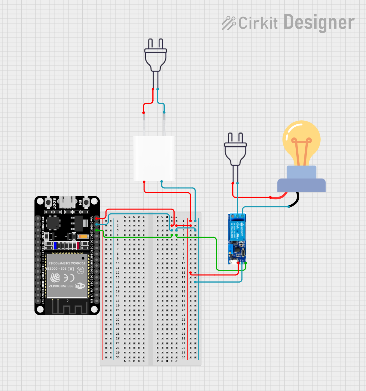
The circuit described is designed to control an AC-powered LED bulb using a microcontroller, specifically an ESP32 (30 pin) module. The circuit includes a 5V adapter to step down the 220V AC power to 5V DC, which powers both the ESP32 and a relay module. The relay module is used to switch the LED bulb on and off. The ESP32 controls the relay module via one of its digital pins. The circuit is powered by two separate 220V AC power sources, one for the LED bulb and one for the 5V adapter.
Component List
LED Bulb AC / Bombillo AC
- Description: An AC-powered LED bulb.
- Pins:
+,-
Power 220V (Source 1)
- Description: A 220V AC power source.
- Pins:
hot wire,neutral wire
Power 220V (Source 2)
- Description: Another 220V AC power source.
- Pins:
hot wire,neutral wire
5V Adapter
- Description: A power adapter that converts 220V AC to 5V DC.
- Pins:
AC In 1,AC In 2,5V,GND
Relay Module 5V-30V
- Description: A relay module that can be triggered by a 5V signal to switch higher voltage circuits.
- Pins:
common contact,normally open,normally closed,trigger,V-,V+
ESP32 (30 Pin)
- Description: A microcontroller with WiFi capabilities, used to control the relay module.
- Pins:
EN,VP,VN,D34,D35,D32,D33,D25,D26,D27,D14,D12,D13,GND,Vin,D23,D22,TX0,RX0,D21,D19,D18,D5,TX2,RX2,D4,D2,D15,3V3
Wiring Details
LED Bulb AC / Bombillo AC
+connected to thenormally openpin of the Relay Module.-connected to thehot wireof Power 220V (Source 2).
Power 220V (Source 1)
hot wireconnected toAC In 1of the 5V Adapter.neutral wireconnected toAC In 2of the 5V Adapter.
Power 220V (Source 2)
hot wireconnected to the+pin of the LED Bulb AC / Bombillo AC.neutral wireconnected to thecommon contactpin of the Relay Module.
5V Adapter
AC In 1connected to thehot wireof Power 220V (Source 1).AC In 2connected to theneutral wireof Power 220V (Source 1).5Vconnected toVinof the ESP32 andV+of the Relay Module.GNDconnected toGNDof the ESP32 andV-of the Relay Module.
Relay Module 5V-30V
common contactconnected to theneutral wireof Power 220V (Source 2).normally openconnected to the+pin of the LED Bulb AC / Bombillo AC.triggerconnected toD13of the ESP32.V+connected to5Vof the 5V Adapter.V-connected toGNDof the 5V Adapter.
ESP32 (30 Pin)
Vinconnected to5Vof the 5V Adapter.GNDconnected toGNDof the 5V Adapter.D13connected totriggerof the Relay Module.
Documented Code
There is no code provided for the ESP32 microcontroller. To complete the circuit functionality, code would need to be written and uploaded to the ESP32 to control the relay module based on the desired logic (e.g., switching the LED bulb on and off based on a schedule or sensor input). The code would typically be written in C or C++ using the Arduino IDE or the ESP-IDF framework and would involve setting up the GPIO pin connected to the relay module as an output and then toggling it to control the state of the relay.