ESP32-Controlled Motion Data Logger with Stepper Motor Actuation
Circuit Documentation
Summary
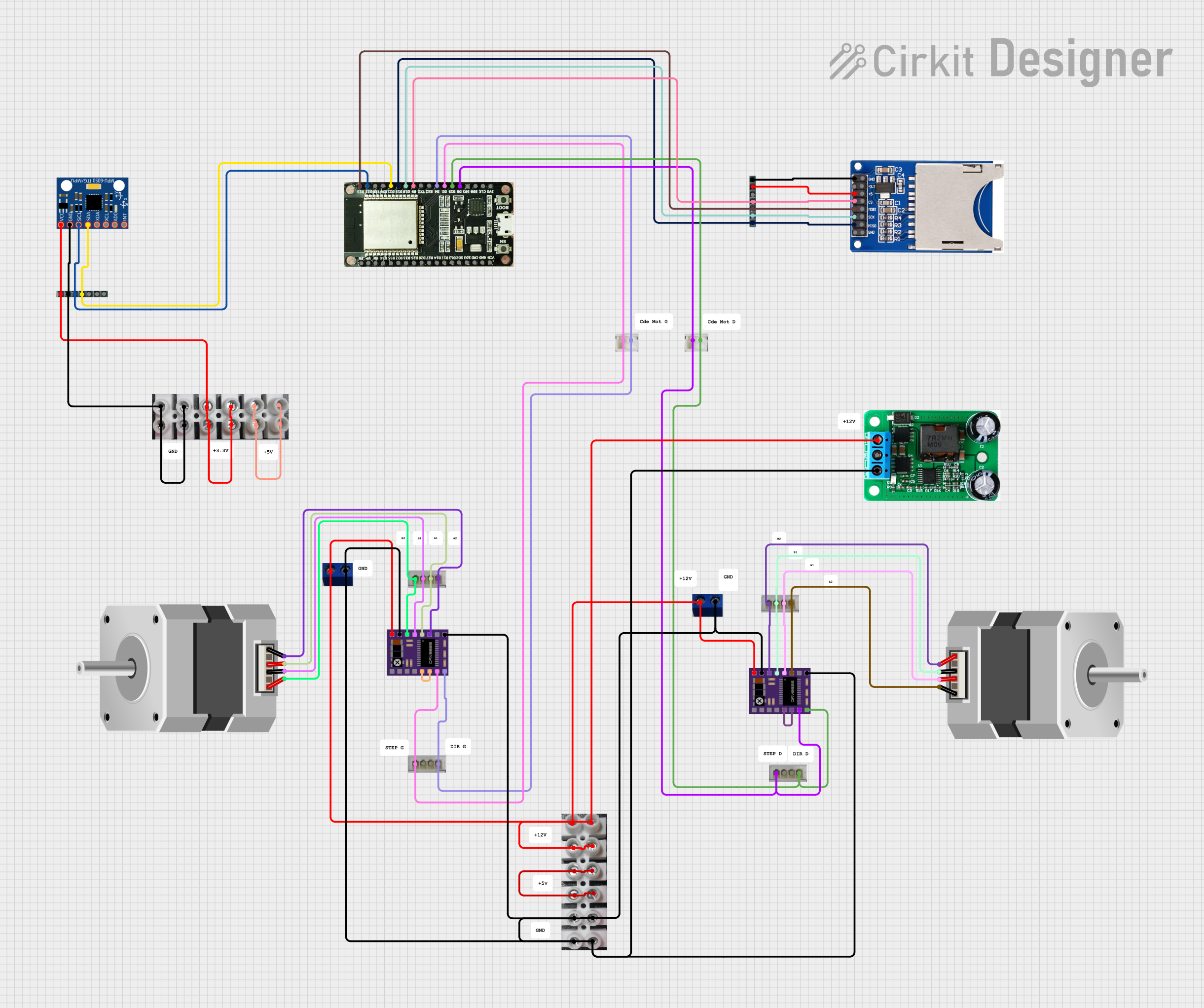
This circuit integrates various components including an ESP32 development board, SD card reader, MPU-6050 sensor, DRV8825 stepper motor drivers, and stepper motors. The ESP32 serves as the central microcontroller, interfacing with the SD card reader for data storage and the MPU-6050 for motion tracking. The DRV8825 drivers control the stepper motors, which could be used for precise motion control in applications such as robotics or CNC machines. The circuit also includes power conversion and connector components to facilitate power distribution and modular connections.
Component List
ESP32-36PINS-DEVKIT-V1
- Description: A development board with an ESP32 microcontroller, featuring a wide range of GPIO pins for interfacing with various peripherals.
- Pins: EN, IO36, IO39, IO34, IO35, IO32, IO33, IO25, IO26, IO27, IO14, IO12, IO13, IO09, IO10, IO11, GND, VIN, 3V3, IO06, IO07, IO08, IO00, IO15, IO02, IO04, IO16, IO17, IO05, IO18, IO19, IO21, IO03, IO01, IO22, IO23
SD-CARD-READER-2PINS
- Description: A module for reading and writing to SD cards, compatible with the ESP32 for data logging or storage.
- Pins: GND, 3.3V, 5V, CS, MOSI, SCK, MISO
MPU-6050
- Description: A motion tracking device that contains a 3-axis gyroscope and a 3-axis accelerometer.
- Pins: VCC, GND, SCL, SDA, XDA, XCL, AD0, INT
DRV8825
- Description: A stepper motor driver capable of driving a bipolar stepper motor with advanced control features like micro-stepping.
- Pins: ENABLE, M0, M1, M2, RESET, SLEEP, STEP, DIR, GND, FAULT, A2, A1, B1, B2, VMOT
Stepper Motor (Bipolar)
- Description: A bipolar stepper motor for precise motion control.
- Pins: D, B, C, A
CONV+12TO+5V
- Description: A power converter that steps down +12V to +5V.
- Pins: +12V, GND, +5V
ConnBlanc4Pins
- Description: A 4-pin connector for modular connections in the circuit.
- Pins: Pin1, Pin2, Pin3, Pin4
ConnBlanc2Pins
- Description: A 2-pin connector for modular connections in the circuit.
- Pins: P1, P2
ConnBleu2PinALIM
- Description: A 2-pin power connector.
- Pins: V+, V-
DOMINOS-6
- Description: A 6-pin connector block used for creating bus-like connections or for distributing power and signals.
- Pins: P1, P2, P3, P4, P5, P6
SIL7
- Description: A 7-pin single in-line (SIL) connector for interfacing or breakout purposes.
- Pins: Pin1, Pin2, Pin3, Pin4, Pin5, Pin6, Pin7
Comment
- Description: A placeholder component used for annotations or comments within the circuit design.
Wiring Details
ESP32-36PINS-DEVKIT-V1
- IO00: Connected to STEP pin of DRV8825 and P1 of ConnBlanc2Pins
- IO15: Connected to DIR pin of DRV8825 and P2 of ConnBlanc2Pins
- IO02: Connected to STEP pin of another DRV8825 and P1 of another ConnBlanc2Pins
- IO04: Connected to DIR pin of the same DRV8825 and P2 of the same ConnBlanc2Pins
- IO05: Connected to CS pin of SD-CARD-READER-2PINS and Pin4 of SIL7
- IO18: Connected to SCK pin of SD-CARD-READER-2PINS and Pin2 of SIL7
- IO19: Connected to MISO pin of SD-CARD-READER-2PINS and Pin1 of SIL7
- IO21: Connected to SDA pin of MPU-6050 and Pin4 of another SIL7
- IO22: Connected to SCL pin of MPU-6050 and Pin3 of the same SIL7
- IO23: Connected to MOSI pin of SD-CARD-READER-2PINS and Pin3 of SIL7
SD-CARD-READER-2PINS
- GND: Connected to Pin7 of SIL7
- 5V: Connected to Pin6 of SIL7
MPU-6050
- GND: Connected to Pin2 of SIL7 and P1 of DOMINOS-6
- VCC: Connected to Pin1 of SIL7 and P3 of DOMINOS-6
DRV8825 (Two Instances)
- STEP, DIR: Connected to ESP32 and ConnBlanc2Pins as described above
- GND: Connected to V- of ConnBleu2PinALIM
- VMOT: Connected to V+ of ConnBleu2PinALIM
- RESET, SLEEP: Internally connected for enabling the driver
- A1, A2, B1, B2: Connected to corresponding pins of Stepper Motor (Bipolar) through ConnBlanc4Pins
Stepper Motor (Bipolar) (Two Instances)
- D, B, C, A: Connected to DRV8825 through ConnBlanc4Pins
CONV+12TO+5V
- +12V: Connected to V+ of ConnBleu2PinALIM and P6 of DOMINOS-6
- GND: Connected to V- of ConnBleu2PinALIM and P1 of DOMINOS-6
- +5V: Connected to V- of ConnBleu2PinALIM
ConnBlanc4Pins and ConnBlanc2Pins
- Used for modular connections between DRV8825 and Stepper Motors, and between ESP32 and DRV8825.
ConnBleu2PinALIM
- V+: Connected to +12V of CONV+12TO+5V and VMOT of DRV8825
- V-: Connected to GND of CONV+12TO+5V and GND of DRV8825
DOMINOS-6
- Used for distributing power (VCC and GND) to MPU-6050.
SIL7
- Used for interfacing SD-CARD-READER-2PINS and MPU-6050 with ESP32.
Documented Code
No code has been provided for the microcontrollers in the circuit. The documentation of the code would typically include descriptions of the functions, initialization routines, and the main control loop, along with any interrupt service routines or peripheral configurations. Since no code is available, this section remains empty.