
Arduino Mega 2560 Controlled RFID and Multi-Color LED Display System
View and Edit Project In Cirkit Designer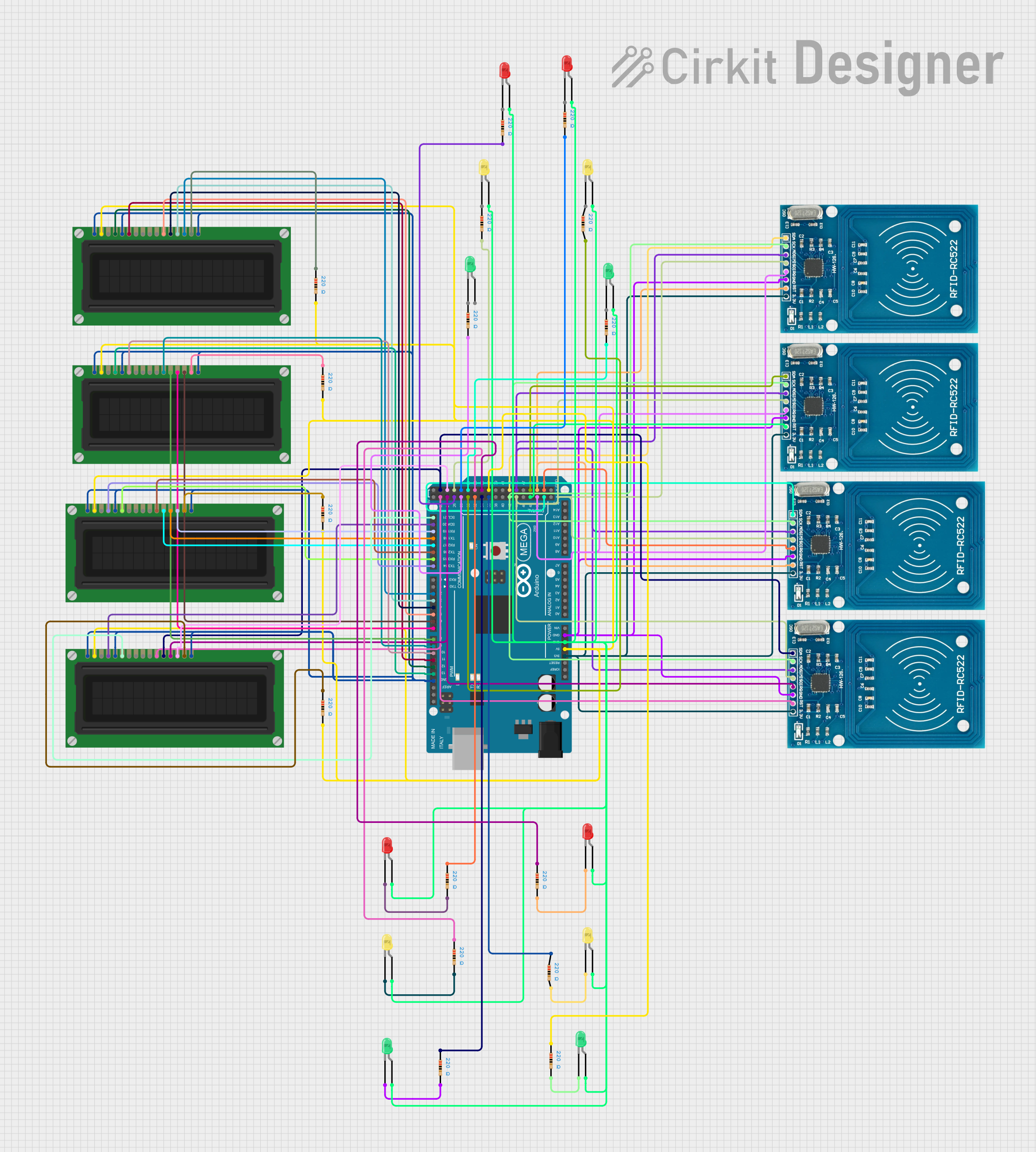
Circuit Documentation
Summary
This circuit incorporates a variety of components including LEDs of different colors, resistors, RFID-RC522 modules, LCD displays, and an Arduino Mega 2560 microcontroller. The circuit is designed to interface RFID modules and LCD displays with the Arduino Mega 2560, which acts as the central processing unit. The LEDs are used as indicators and are connected with resistors to limit the current. The RFID modules are likely used for wireless communication or identification purposes. The LCD displays are used to provide a user interface or display information.
Component List
LEDs
- LED (Green): A two-pin green light-emitting diode used as an indicator.
- LED (Red): A two-pin red light-emitting diode used as an indicator.
- LED (Yellow): A two-pin yellow light-emitting diode used as an indicator.
Resistors
- Resistor: A passive two-pin component with a resistance of 220 Ohms, used to limit current through the LEDs.
RFID Modules
- RFID-RC522: A radio frequency identification (RFID) reader module with pins for power (VCC), reset (RST), ground (GND), interrupt (IRQ), Master In Slave Out (MISO), Master Out Slave In (MOSI), Serial Clock (SCK), and Serial Data (SDA).
LCD Displays
- LCD Display (16 pin): A liquid crystal display with 16 pins including power (VDD, VSS), contrast (VO), register select (RS), read/write (R_W), enable (E), data bits (DB0-DB7), and backlight (A, K).
Microcontroller
- Arduino Mega 2560: A microcontroller board based on the ATmega2560 with numerous digital and analog I/O pins.
Wiring Details
LEDs
Each LED has an anode and cathode pin. The anode is connected to a digital pin on the Arduino Mega 2560 through a 220 Ohm resistor, and the cathode is connected to the ground (GND).
Resistors
Each resistor has two pins, pin1 and pin2. Pin1 of each resistor is connected to a digital pin on the Arduino Mega 2560, and pin2 is connected to the anode of an LED or the VDD pin of an LCD display.
RFID Modules
Each RFID-RC522 module's VCC pin is connected to the 3.3V output on the Arduino Mega 2560. The GND pin is connected to the ground (GND) on the Arduino. The SDA, IRQ, MISO, MOSI, SCK, and RST pins are connected to specific digital pins on the Arduino Mega 2560.
LCD Displays
Each LCD display's VDD pin is connected to the 5V output on the Arduino Mega 2560 through a 220 Ohm resistor. The VSS, K, and R_W pins are connected to the ground (GND). The RS, E, DB4, DB5, DB6, and DB7 pins are connected to specific digital pins on the Arduino Mega 2560. The A pin is connected to the 5V output on the Arduino Mega 2560 through a 220 Ohm resistor.
Documented Code
The code provided is for the Arduino Mega 2560 microcontroller. It includes a basic structure with empty setup() and loop() functions, which are placeholders for initialization code and the main program logic that will run repeatedly.
void setup() {
  // put your setup code here, to run once:

}

void loop() {
  // put your main code here, to run repeatedly:

}
The setup() function is called once when the microcontroller is powered on or reset. It is used to initialize variables, pin modes, start using libraries, etc. The loop() function is called repeatedly and contains the main logic of the program.
The additional file named "documentation.txt" is empty and does not contain any code or comments.