
Arduino and ESP8266-Based Battery Monitoring and Temperature Control System with Wi-Fi Connectivity
View and Edit Project In Cirkit Designer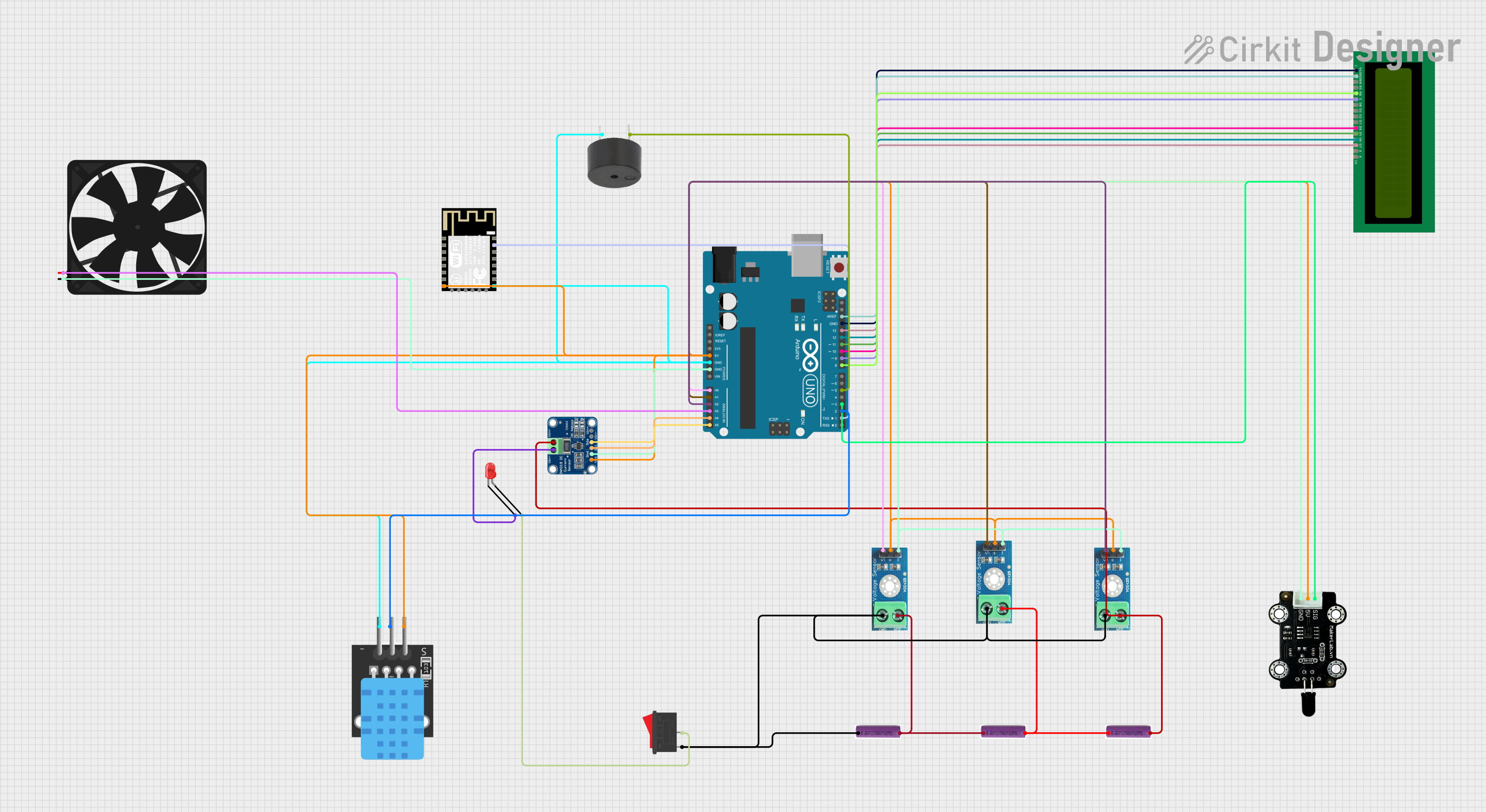
Circuit Documentation
Summary
This circuit is designed to monitor and display various parameters such as voltage, current, temperature, and fan status. It uses an Arduino UNO as the main microcontroller, interfaced with an ESP8266 WiFi module for wireless communication, multiple voltage sensors, a temperature sensor, a flame sensor, an INA219 current sensor, an LCD display, a buzzer, and a fan. The circuit is powered by three 3.7V batteries.
Component List
ESP8266 ESP-12F WiFi Module
- Description: WiFi module for wireless communication.
- Pins: GND, GPIO15, GPIO2, GPIO0, GPIO4, GPIO5, RXD0, TXD0, RST, ADC0, EN, GPIO16, GPIO14, GPIO12, GPIO13, VCC, SCLK, MOSI, GPIO10, GPIO9, MISO, CS0
3.7V Battery
- Description: Power source for the circuit.
- Pins: +, -
Arduino UNO
- Description: Main microcontroller for the circuit.
- Pins: UNUSED, IOREF, Reset, 3.3V, 5V, GND, Vin, A0, A1, A2, A3, A4, A5, SCL, SDA, AREF, D13, D12, D11, D10, D9, D8, D7, D6, D5, D4, D3, D2, D1, D0
Voltage Sensor DC 25V
- Description: Measures voltage up to 25V.
- Pins: +, -, output, gnd, vcc
MKE-S04 IR Infrared Flame Sensor
- Description: Detects flame presence.
- Pins: SIG, 5V, GND
INA219
- Description: Current sensor.
- Pins: VCC, GND, SCL, SDA, VIN -, VIN +
LED: Two Pin (red)
- Description: Indicator LED.
- Pins: cathode, anode
Fan
- Description: Cooling fan.
- Pins: GND, 5V
Rocker Switch
- Description: On/Off switch.
- Pins: 1, 2
16X2 LCD
- Description: Displays information.
- Pins: VSS, VDD, V0, RS, RW, E, D1, D0, D2, D3, D4, D6, D5, D7, A, K
TEMP
- Description: Temperature sensor.
- Pins: 5V, D3, GND
Buzzer
- Description: Audible alert.
- Pins: PIN, GND
Wiring Details
ESP8266 ESP-12F WiFi Module
- GND: Connected to GND of Arduino UNO, TEMP, and Buzzer.
- RXD0: Connected to D1 of Arduino UNO.
- VCC: Connected to 5V of Arduino UNO, TEMP, INA219, Flame Sensor, and Voltage Sensors.
3.7V Battery
- +: Connected to vcc of Voltage Sensor DC 25V.
- -: Connected to gnd of Voltage Sensor DC 25V and Rocker Switch.
Arduino UNO
- GND: Connected to GND of TEMP, ESP8266, Buzzer, Voltage Sensor DC 25V, INA219, Fan, Flame Sensor, and LCD.
- D1: Connected to RXD0 of ESP8266.
- 5V: Connected to + of Voltage Sensor DC 25V, TEMP, INA219, ESP8266, Flame Sensor, and Fan.
- A0: Connected to output of Voltage Sensor DC 25V.
- A1: Connected to output of Voltage Sensor DC 25V.
- A2: Connected to output of Voltage Sensor DC 25V.
- A3: Connected to 5V of Fan.
- A4: Connected to SCL of INA219.
- A5: Connected to SDA of INA219.
- AREF: Connected to VDD of LCD.
- D13: Connected to D7 of LCD.
- D12: Connected to D6 of LCD.
- D11: Connected to D5 of LCD.
- D10: Connected to D4 of LCD.
- D9: Connected to E of LCD.
- D8: Connected to RW of LCD.
- D5: Connected to PIN of Buzzer.
- D3: Connected to SIG of Flame Sensor.
- D2: Connected to D3 of TEMP.
Voltage Sensor DC 25V
- +: Connected to 5V of Arduino UNO, TEMP, INA219, ESP8266, Flame Sensor, and Fan.
- gnd: Connected to GND of Arduino UNO, Rocker Switch, and 3.7V Battery.
- output: Connected to A0, A1, and A2 of Arduino UNO.
- vcc: Connected to + of 3.7V Battery.
MKE-S04 IR Infrared Flame Sensor
- SIG: Connected to D3 of Arduino UNO.
- 5V: Connected to 5V of Arduino UNO.
- GND: Connected to GND of Arduino UNO.
INA219
- VCC: Connected to 5V of Arduino UNO.
- GND: Connected to GND of Arduino UNO.
- SCL: Connected to A4 of Arduino UNO.
- SDA: Connected to A5 of Arduino UNO.
- VIN +: Connected to + of 3.7V Battery.
- VIN -: Connected to cathode of LED.
LED: Two Pin (red)
- cathode: Connected to VIN - of INA219.
- anode: Connected to 2 of Rocker Switch.
Fan
- GND: Connected to GND of Arduino UNO.
- 5V: Connected to A3 of Arduino UNO.
Rocker Switch
- 1: Connected to gnd of Voltage Sensor DC 25V.
- 2: Connected to anode of LED.
16X2 LCD
- VSS: Connected to GND of Arduino UNO.
- VDD: Connected to AREF of Arduino UNO.
- D7: Connected to D13 of Arduino UNO.
- D6: Connected to D12 of Arduino UNO.
- D5: Connected to D11 of Arduino UNO.
- D4: Connected to D10 of Arduino UNO.
- E: Connected to D9 of Arduino UNO.
- RW: Connected to D8 of Arduino UNO.
TEMP
- 5V: Connected to 5V of Arduino UNO.
- D3: Connected to D2 of Arduino UNO.
- GND: Connected to GND of Arduino UNO.
Buzzer
- PIN: Connected to D5 of Arduino UNO.
- GND: Connected to GND of Arduino UNO.
Documented Code
#include <Wire.h>
#include <Adafruit_INA219.h>
#include <LiquidCrystal.h>
#include "DHT.h"

int vval;
int cnt=0;
const int rs = 8, en = 9, d4 = 10, d5 = 11, d6 = 12, d7 = 13;
LiquidCrystal lcd(rs, en, d4, d5, d6, d7);
Adafruit_INA219 ina219;
float R1 = 30000.0;  // Adjust these values if needed for correct scaling
float R2 = 7500.0;
// Reference voltage for ADC (use 3.3V for ESP8266)
float ref_voltage = 3.3;
#define DHTPIN 2      // DHT sensor pin
#define DHTTYPE DHT11 // DHT sensor type
DHT dht(DHTPIN, DHTTYPE);
int buz = 5;
int rly = 2;
int mot1 =A3;
int fs = 3;

void setup(void) {
  Serial.begin(9600);
  pinMode(mot1, OUTPUT);
  pinMode(rly, OUTPUT);
  pinMode(fs, INPUT);
  lcd.begin(16, 2);
  pinMode(buz, OUTPUT);
  digitalWrite(buz, 0);
  lcd.print("  WELCOME ");
  dht.begin();

  if (!ina219.begin()) {
    Serial.println("Failed to find INA219 chip");
    while (1) { delay(10); }
  }
}

void loop(void) {
  cnt++;
  // Read main voltage, current, power from INA219
  float shuntvoltage = ina219.getShuntVoltage_mV();
  float busvoltage = ina219.getBusVoltage_V();
  float current_mA = ina219.getCurrent_mA();
  float power